15
Connect a clean water supply pipe to the
water mains, checking to ensure that the
minimum pressure is of 1.5 bar and maxi-
mum is of 6 bar, with a minimum ow rate
of 7 l per min.
- Connect the water supply pipe (min. diam ½”) to
the water mains (Fig. 2)
- Screw the male connector (Fig. 3) on to the at-
tachment of the water supply (2); snap the female
connector of the tube (3) on to the connector.
3 CONNECTION OF THE WATER SUPPLY PIPE
Based on the prescriptions and provisions
set forth by the regulations currently in
force, it is mandatory that the appliance
is never operated without a potable water
backow preventer device, connected up to the
potable water supply mains. Use a suitable potable
water backow preventer device, compliant to the
EN 12729 type BA standard provisions. Water that
ows through a system backow preventer cannot
be classied as potable water.
4 HIGH PRESSURE PIPE CONNECTION
- Unwind the pressure hose o the hose drum (Fig.
4).
- Screw the high pressure tube on to the gun (Fig.
5).
5 ELECTRICAL CONNECTION OF THE AP-
PLIANCE
The mains voltage must match the operating volta-
ge. (See identication plate)
Insert the plug into a power socket installed in
compliance with regulations.
Check the minimum section of the individual cables
using extensions.
Position the extensions so as to maintain the pro-
tection class of the equipment.
Voltage Cable Cross-section
V length m mm
2
230 up to 2 1,5
230 20 to 5 2,5
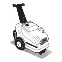
6 APPLIANCE ACTIVATION
Operate the equipment in vertical position
(Fig. 7) only after connecting the water
supply pipe and turning on the tap.
- Position the switch on I (ON) (Fig.8).
- Position the spray gun on the object to be
cleaned - never on people !
- Press the safety device (Fig.9) - the gun is released
- Direct the nozzle downwards (Fig.7)
- Fully press down the trigger (Fig.7)
7 SWITCHING OFF THE MACHINE
- Position the switch on O (OFF) (Fig.8).
- Turn o water supply tap.
- Actuate spray gun until water drips from the
nozzle (machine is now de-pressurized).
- Release trigger.
- Press safety latch on spray gun. (Fig.9). The
spray gun is locked and cannot be actuated
accidentally.
- Unplug machine from socket outlet.
- Disconnect water supply hose from machine and
water supply mains.
8 ACCESSORIES
Variable nozzle
The nozzle (Fig.10) can be regulated in a conti-
nuous manner, by rotating the regulation bushing,
changing it from a pinhole jet (Fig.10) to a at jet
and viceversa.
It can be used at either high or low pressure by
shifting the head in a longitudinal sense according to
the direction of the arrow on the head itself (Fig. 11).
ADDITION OF DETERGENT
The detergents must not be allowed to
dry on the object to be cleaned.
The product is tted with one detergent
tank.Fill the detergent tank (Fig. 12) with detergent,
dilute as recommended.
Winder kit
The rotation sense for the winding of the high pres-
sure hose is only permitted in a clockwise direction.
(Fig. 13).
9 MAINTENANCE , REPAIRS AND STORAGE
Before undertaking any work
on the appliance always de-
tachthe plug from the power
socket
Undertake only the maintenance operations descri-
bed in the user instructions.
Contact the Technical Assistance service for all other
interventions.
Use only original spares.
Should the power cable be damaged, it must be
replaced by a cable or a set of special cables avai-
lable from the manufacturer or its assistance service.
The pins and joints of the connection cables of the
electrical system must be protected against accidental
water sprays.
Cleaning/inspecting the strainer
Expose the strainer (Fig.14) in the machine water