-5-
Generally speaking the pins to use are as follows:-
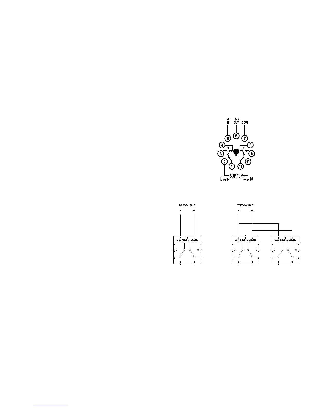
Voltage inputs and externally sourced current inputs. Pin 5 + Pin 7 -
Internally sourced current inputs Pin 6 + Pin 5 -
eg. Two- wire transmitters powered from this unit.
INPUT INFORMATION
Voltage inputs are high impedance, typically better than 50kohms/volt. Units may
be connected in parallel to obtain more set points.
Current inputs are 250 ohm as standard. This allows a high impedance 1-5V
voltmeter to be connected across terminals 5 & 7 when indication is required.
Units may be connected in series to obtain more set points. When using the
internal 24V power supply, only one unit should power the loop (from pin 6). The
other units must be wired for external supply operation. (See drawings on page 7)
When connecting units in series, each unit will drop 5 volts at 20mA. As most
4-20mA loops are powered from 24V DC there is the possibility of having
insufficient voltage available to power everything in the loop. Lower impedance
units are available to special order in 100ohm, 47ohm & 22ohm. These can be
identified by their part numbers, ie. 1200-100 is the 100ohm version.
-6-
CONNECTION DIAGRAM
VOLTAGE INPUTS
 Loading...