Camera Address (continued...)
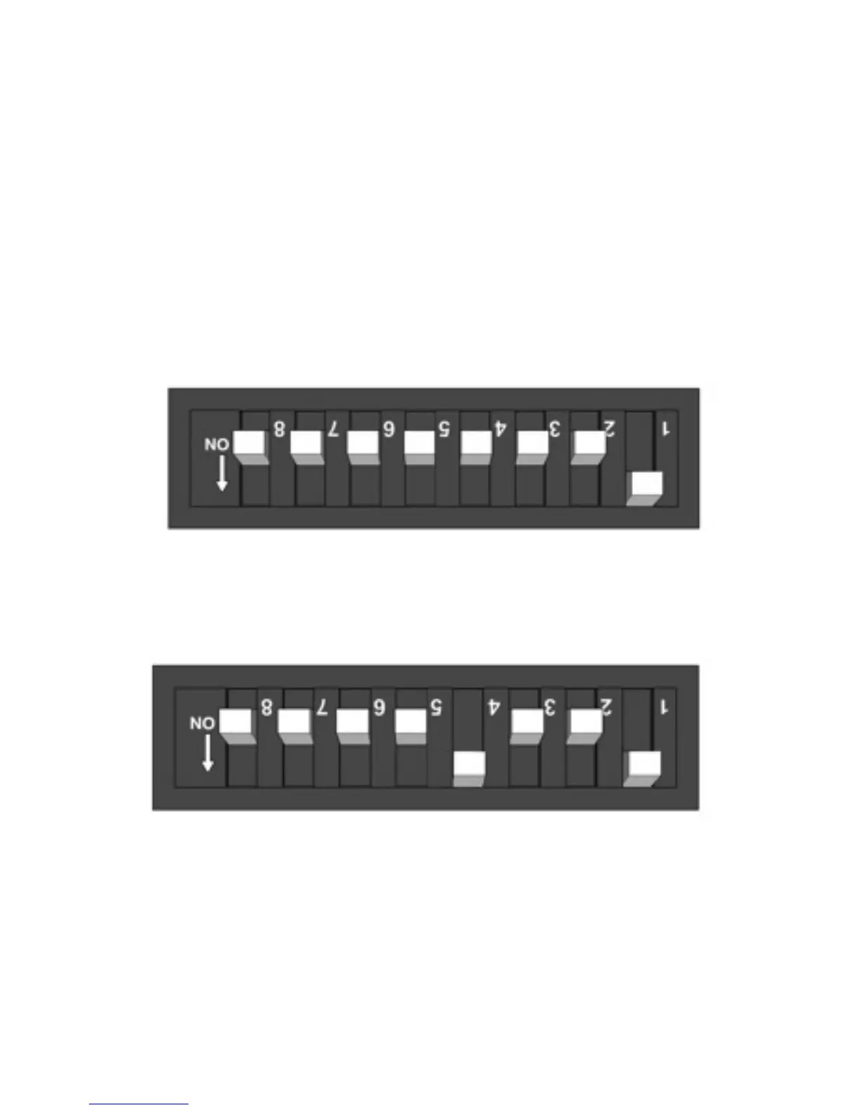
The example below (Fig 3.0) shows the camera address set to 1, as switch 1 is
set to the ON position as shown by the arrow. As the switches set the binary
address, to set the cameras address to 2, set switch 1 to OFF and switch 2 to
ON. To set the camera to address 3, ensure both switches 1 and 2 are set to
the ON position. For address 4, switches 1 and 2 should be OFF and switch 3
should be ON. The value of each switch doubles. The value of each individual
switch is listed below:
Switch 1 = 1. Switch 2 = 2. Switch 3 = 4. Switch 4 = 8. Switch 5 = 16. Switch
6 = 32. Switch 7 = 64. Switch 8 = 128
Fig.3.0: Example of Camera Address set to 1
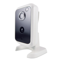
Fig.3.1: Example of Camera Address set to 9. Switch 1 has a value of 1 and
switch 4 has a value of 8, therefore 1 + 8 = 9
Iris Innovations: IRIS106 User Guide. v1.00 072013