4.3. CAMERA CABLE PACKAGE
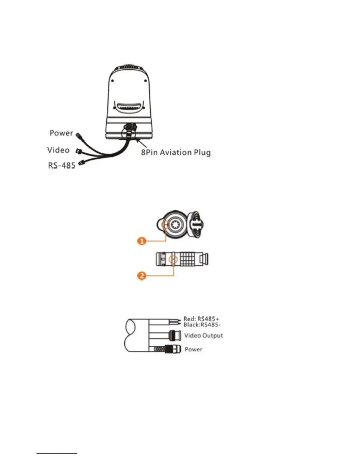
Connect the cable observing correct polarity as per following diagrams:
Fig. 11: Cable Package
There are two red marks each on the plug and socket. Please match them during connection:
Fig. 12: Cable Connection 1
Connect correct cables to relative outputs (RS485 +/-, Video Output and Power):
Fig. 13: Cable Connection 2
Please ensure correct polarity is observed at all times when connecting cables. Failure to do so could result in
irreparable damage to the camera, surrounding vessel and even injury.