Spezialelektronik GmbH
iseg Spezialelektronik GmbH Email: sales@iseg-hv.de Phone ++ 49 (0)351 / 26 996 – 0
Bautzner Landstr. 23 http://www.iseg-hv.com Fax ++ 49 (0)351 / 26 996 – 21
12 D - 01454 Radeberg / Rossendorf Germany
4.2.3 Transition manual control Ù remote control
In manual control mode the internal control voltage is depending on the effective output voltage. Therefore only very low
voltage drops occur during transition to remote control mode.
During transition from remote control mode to manual control mode, the output voltage will change to the value set with the
voltage control potentiometer with a voltage ramp of 500V/s
During transition from remote control mode to manual control mode, the output voltage will
change to the value set with the voltage control potentiometer with a voltage ramp of 500V/s. This
can affect the application.
4.3 Current measurement ranges
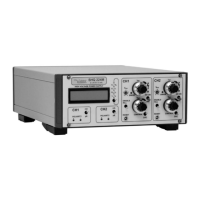
Each channel has two current measurement ranges. The range can be chosen with the switch labeled with “mA” and “µA” in
the channel control field under the display. In “mA” position, there is an automatic switching between the current
measurement ranges in case of crossing of the threshold. In position “µA” current measurement will stay in the “µA” range, in
case of measurements higher than the threshold “Overflow” will be displayed.
4.3.1 Current measurement ranges and current trip
With the current measurement range switch it is also chosen which current trip is active.( see chapter 4.4)
• Position „mA“
The commands Lx and LBx are active
• Position „µA“
The command LSx is active
4.4 Safety functions
Each channel has separate safety functions
• Hardware-voltage limit V
max
The maximum output voltage can be selected in 10%-steps with the rotary switches V
max
(switch dialed to 10
corresponds to 100%). The output voltage is then limited to V
max
.
• Hardware-current limit Imax
The maximum output current for each channel can be selected in 10%-steps with the rotary switches I
max
(switch dialed
to 10 corresponds to 100%) Depending on the position of KILL switch, the unit switches into current control mode or the
channel is switched Off
Option IWP: With this Option, the 10 percent switch of Imax is replaced with a 10-turn
potentiometer. Smaller steps for current limitation are possible.

 Loading...