e
{Fig.
12)
(Fig.
61
(Fig.
81
Change
lever
Levier
de
changement
de
vite55es
Element
Element
IFig.
111
IFig.71
(Fig.
101
(Fig_
91
Bolt
Boulon
Plaque
Dust-proof Spacer
late t t .
5-1
Nettoyage des bougies
Comme
la
bougie
peut
facilement
S8
deteriorer
par
Ie
depot
de
calamine, il
faut
de temps
en
temps
enlever
la
bougie
et
la
nettoyer.
Ajuster
I'ecartement
des electrodes a
0.6-0.7
mm.
(Fig.6)
5-2 Nettoyage du filtre d'air
Apres avoir
depose
I'attache
du
boitier,
retirer
les
deux
elements
at
I'entretoise.
Utiliser
un
mrange
d'huile
pour
Ie
nettoyage
des
elements,
puis
les
replacer apres
les
avoir
saches. Apres avoir
nettoye
I'entretoise avec
de
I'huile,
appliquer
de
I'huile
moteur
sur
sa
partie
en
feutre
at
replacer 1
7
entretolse
a sa
position
originale. Laisser
la
plaque et
Ie
couvercle anti-poussiere respectivement sur
Ie
carburateur.
Dans des
conditions
de
travail
normales,
nettoyer
Ie
filtre
d'air
une fois par
semaine;
proceder
a
un
examen
ou
a un
nettoyage
chaque
jour
si
la
machine
traville
dans
un
environnement
tres poussiereux.
(Fig.7)
5-3
Nettoyage
du
demarreur
arecul
En cas
de
fonctionnement
irregulier
dj'
demarrage
arecul en raison
d'encrassement
d,.
boue
et
de
salete,
il
faut
enlever celles-ci
du
carenage en
detaisant
les trois
boulons
de
fixation.
(Fig.
81
Enlever
la
boue
et
la
salete
accrochees
autour
de
la
roue
de
la
corde;
bien lubrifier les
Lock
lever
Levier
de
reglage
pieces rctatives
et
frottantes
(specialement
autour
de
I'axe)
et
s'assurer
de
la
bonne
motilite
de
I'operation.
,~~,
_~.
) 5-4
Pivotement
du
guidon
a
droite
ou
a
____
\L_~·::'~-=:;c:::,;._J
gauche
__
A~
""
Relikher
Ie
bouton
de
blocage
situe
aI'avant
.','0
du
chassis
de
poignee.
II
est
possible
d'obtenir
un
ajustement
en
trois
positions,
soit
a
droite
Setting bolt
soit
a gauche, en
serrant
Ie
levier
de
reglage.
Boulon
de
niglage
Choisir
la
position
la
mieux
appropriee
pour
Ie
travail a
executer.
(Fig.9)
5-5
Pivotement
du
guidon
a
180
degres
En
serrant
de
la
main
Ie
levier
de
n§glage,
il
est
possible
d'effectuer
sur
Ie
cote
gauche
un
deplacement du guidon a180°. (Fig. 9)
Note:
Apres avoir
effectue
un
deplacement,
quelconque
du
guidon,
il
faut
resserre(i
Ie
bouton
de
blocage
comme
il
etait. -
Remarquer
qu'il
est
impossible
de
faire
pivoter
Ie
guidon
completement
sur
la
droite.
5-6
Deplacement
du
levier
de
changement
de
vitesse
En levant
Ie
levier
de
changement
de
vitesse
et
Chan,ge
mark en
I.e
.tournan~
~ers
la
gauche,
il
est
possible
de
Re'pere
de
cholslr sa POSition. (Fig. 10)
chang~ment
Les
positions
de
changement
de
vitesse
sont
de
vltesses
celles qui
sont
indiquees par des reperes Sur
i
Ch
I
Ie
guide de changement de vitesse (Fig. 12).
ange
ever
•..
. ,
Change
J..._~!~Jj
En
temps
Le
point
de
controle
de
vltesse Indlque
sur
gUide
-------------1
4:<
normal
la
Fig.
12
(position
marquee
par un
"0")
Guide
de
When
being
normal
represente
la
premiere
vitesse en
marche
changement
Levier
de
changement
avant
si
Ie
levier
de
changement
se
troube
de
vitesses
a
la
position
normale;
il
represente
la
premiere
vitesse
en
marche
arriere
si
Ie
levier
de
change-
ment
est
tourne
une
fois.
5-7
Ajustement
de
hauteur
du
guidon
Le
guidon
du
motoculteur
peut
etre
ajuste
en
hauteur
pour
correspondre
de
fac;:on
longitu-
dinal
a
la
taille
de
la
personne
qui utilise
I'appareil
ou
au travial a
effectuer.
Pour
ajuster
a
la
bonne
hauteur,
il
faut
desserrer
Ie
bouton
de
blocage
et
Ie
resserrer apres avoir
place
Ie
guidon
a
la
hauteur
voulue. (Fig. 10)
5-8
Ajustement
d'embrayage
et
des sections
concernees
~
\O"''''
.~
~.-'~--'.'
Butee
de
-....-....~_.
0
courroie 0
When
operating
Pendant
Ie
fonctionnement
Change
lever
En
temps
~
normal
D
,
~
5-1
Cleaning
of
the
spark
plug
Since
the
spark plug
is
apt
to
get
dirt
with
carbon
or
others,
clean it by
sometime
taking
it
out.
Adjust
the
electrode
clearance
of
the
spark
plug
to
be
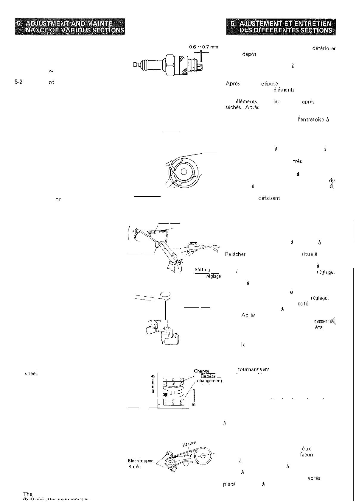
0.6 - 0.7 mm. (Fig.
7)
5~2
Cleaning
of
the
air
cleaner
By removing
the
catcher
of
the
housing,
take
out
both
the
elements
and
the
spacer. Use
mixed
oil
to
clean
the
elements
and replace
them
after
fully
drying.
After
cleaning
the
spacer
with
mixed oil,
apply
engine oil
to
its
felt
portion
and replace
the
spacer
to
the
original
location.
Keep
the
plate
and
the
dustproof
plate
mounted
on
the
carbureter,
respectively. Clean
the
air cleaner
once
a
week
in
the
ordinary
operating
conditions,
or
conduct
cleaning
and
inspection
every
day,
if
the
tiller
is
used
in
a
dusty
environment.
(Fig.7)
5-3 Cleaning
of
the
recoil
starter
In
case
of
unsmoothed
operation
of
the
recoil
starter
due
to
mud
or
dirt
clogged,
take
it
out
of
the
spiral case by releasing
three
fitting
bolts. (Fig. 8)
Removing
mud
or
dirt
clogged
around
the
rope
reel and
the
like,
lubricate
every
rotating
and sliding
portions
(especially
around
the
shaft) and
confirm
the
smoothness
of its
operation.
5-4
Rightward
or
leftward
turnig
of
the
handle
Loosen
the
set
bolt
located
at
the
front
of
handle
frame. 3-stage angle
adjustment
toward
Setting knob
either
side, right
or
left,
can
be
available
with
Bouton
de
blocage
the
lock lever installed
in
the
center
of
the
handle.
Choose
the
best
position
mostly
suit-
able
to
the scheduled
work.
(Fig. 9)
5-5
180
degree
turning
of
the handle
180
degree
turning
of
the
handle
can
be
available
by
holding
the
lock lever
located
in
the
center
of
the
handle
and
by
moving
the
handle leftward. (Fig. 9)
(Notel
Retighten the setting
bolt
as
it
was.
after
any
turning
of
the
handle has
been
completed.
Note
that
the
handle
can
not
be
turned
rightward.
5-6
Turning
of
the
change
lever
When
the
change lever
is
lifted
up
and
turned
leftward,
an
attempting
position
can
be at-
tained. (Fig. 10)
The
speed
controlling
positions
are as indi-
cated
by
the
change
marks
provided
on
the
change guide (Fig.
121
The
step
of
speed
control
shown
in
Fig.
12
(the
position
marked
with
0)
represetns
the
first forward speed
if
the
change
lever
is
set
to
the
normal
position,
or
the
first reverse
speed
if
the
change
lever
is
turned
once.
5-7
Height
adjustment
of
the
handle
Height
adjustment
of
the
handle
can
be
available
to
fit
to
the
personal height
or
the
working
condition,
by
or
in
which
the
tiller
is
operated.
The
adjusting
method
is
to
loosen
the
setting
knob,
and
then
position
the
handle
at
the
best
suitable
height
before
retightening
the
knob.
(Fig.
101
5-8



 To Next Page
 Loading...