EasyManua.ls Logo

Isel CSD 405-IMC User Manual

Isel CSD 405-IMC
4 pages
To Next Page IconTo Next Page
Page #1 background imageLoading...
Page #1 background image
Document 383025 xxxx MD 01204
Wiring and Operation Manual
4-axes step motor controller
CSD 405-IMC
®
-
-
Compact powerful unit to drive up to four 2-phase step motors
CNC / DNC operation through internal microcontroller, flash data memory
- Interpolation modes: linear and circular, helix-interpolation optional
- Motor output 30V/2A per motor, step resolution 1600 steps/revolution
- 300VA power supply with emergency stop circuit according to EN 60204, emergency
stop switching element, Power button, cover switch-output
- 2 freely usable signal inputs (+24V active)
- 2 freely usable switching outputs (relay, +24 switching, 50mA)
- 2 AC outputs (1 relay output 5A, 1 solid-state relay 1.25A)
- Motor connection on the rear via 9-pin Sub-D socket plug
- Dimensions: w x h x d - 274 x 152 x 300mm
- Programmable through the software products: PAL-PC, PAL-PC 2.0 (Windows), ProNC
systro GmbH
Sachsenweg 8 D-36132 Eiterfeld
Tel.: (0 66 72) 898 620 E-Mail: sales@systro.de
l
l
l
l
www.systro.de
l
systro GmbH - a member of isel group
systro
Electronics for systems
Question and Answer IconNeed help?

Do you have a question about the Isel CSD 405-IMC and is the answer not in the manual?

Isel CSD 405-IMC Specifications

General IconGeneral
Axes4
TypeStepper motor controller
Input voltage24-48 V DC
Microstep resolutionup to 1/256
Communication interfaceCANopen
Protection featuresOvervoltage, overcurrent

Summary

Safety Information

Front Panel Controls and Indicators

POWER Button

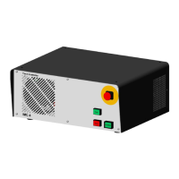
Activates the integrated power relay, switching on voltage supply to the output stage. The POWER lamp indicates operation.

START Button

Initiates the program sequence after a stop command or starts a stored program sequence from storage mode.

Emergency Stop

Disengages the voltage supply to the output stage. Pull the button out to unlock its lock-in position.

Rear Panel Connections

Motor Outputs

Connects 2-phase step motors via 9-pin Sub-D connectors, specifying phase and reference switch connections.

User I/O and RS 232

Provides inputs, outputs, and serial communication interface for controller programming and integration.

SK Control and Cover Switch

Interfaces for SK control via 15-pin Sub-D and optional cover switch functionality.

AC Outputs

Offers switched AC 230V outputs via a relay (5A) and a solid-state relay (1.25A).

EC Declaration of Conformity