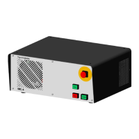
Rear view
- switched AC 230V output.
The output is protected on the
internal control assembly by a
time-lag fuse 5A (HBD, 5x20mm).
AC Output X5
- switched AC 230V output.
The output is protected on the
internal control assembly by a
time-lag fuse 1.25A (HBD)
AC Output X6
(solid-state-relay)
Motor output X1 X4
9-pin Sub-D socket plug()
1
5
6
9
Reference switch
GND (Brake) **
Limit +
+24V (Brake) **
+24V/50mA
Motor phase 1A
Motor phase 1B
Motor phase 2A
Motor phase 2B
Output 2
+24V/0,25A
Output 1
+24V/0,25A
+24V
Input 2 (+18V ... +30V/10mA)
Input 1 (+18V ... +30V/10mA)
+24V
GND
GND
Power button (13)
Emergency stop (11)
Operating mode (23)
Operating mode (24)
Emergency stop (12)
Operating mode (23)
Power button (23)
Emergency stop (21)
Power button (14)
COVER button (13, a)
COVER button (14, b)
Not occupied
Operating mode (24)
Power button (24)
Emergency stop (22)
1
8
9
1
5
Emergency-Stop - switches off the supply
voltage to the power output stage.
12
22
11
21
(5)
(15)
(2)
(8)
Power-button - switches on the supply
voltage to the power output stages,
if there is no Emergency Stop
situation.
14
24
13
23
(9)
(14)
(1)
(7)
Operating mode- switches from automatic
to test operation
14
24
13
23
(4)
(13)
(3)
(6)
Cover button - unlocks the optional cover
switch with tumbler
14
b
13
a
(11)(10)
SK control
(15-pin Sub-D socket plug)
E1
A2
A1
E2
E3
A3 E4 A4
bipolar-serial bipolar-parallel
Example: 2-phase step motor (8-conductors)
(4)
(3)
(2) (1)
(4)
(3)
(2) (1)
(9)
(7)
(5)
Reference switch
Limit +
systro GmbH
Sachsenweg 8 D-36132 Eiterfeld
Tel.: (0 66 72) 898 620 E-Mail: sales@systro.de
l
l
l
l
www.systro.de
l
--
--
--
Cover unlock A2
Contact 11
Contact 12
Contact 21
Contact 22
Cover unlock A1
1
5
6
9
Safety interlocks (cover switch) together
with special operating and evaluation
units comply with the control category
3 or 4.
Cover switch X6
(9-pin Sub-D socket plug)
(2)
(3)
21
(4)
(5)
A1
A2
(1)(6)
22
11
12
AC (Out) AC (Out)
Protective conductor
AC (Out) AC (Out)
Protective conductor
E1
A2
A1
E2
E3
A3 E4 A4
User I/O
(Phönix, MC 3,81, 8pol.)
X5
X6
Z-Axis X-Axis
4.Axis Y-Axis
User I/O
Locking
Safety-Switch
X1 X2
X3 X4
RS 232
(Relay switched)
(12)
** after seiral number 178529
Output 2
+24V /200mA
Output 1
+24V /200mA
( max. 20mA) +24Vout
(+18V.. +30V/ 10mA) Input 2
(max. 20mA) +24Vout
GND
GND
(+18V.. +30V/ 10mA) Input 1
** only at motor output of z-axis (X1),
after serial number 178529
 Loading...