83,5 (*)
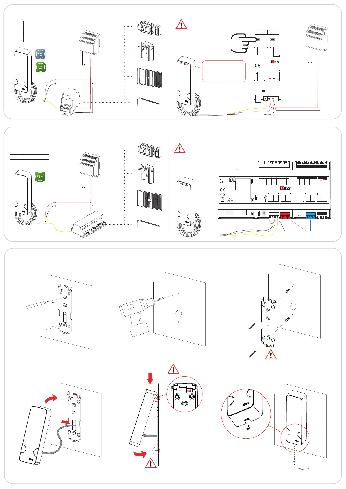
MULLION LOCKBUS: Stand-Alone Gate electrical connection example
Actuator wiring diagram and exchange of coded keys
Vin
230Vac
Vout
12Vdc
Power
supply
Power
supply
Vin
Vout
12Vdc
Mullion
Lockbus
WHITE Power supply +
BROWN Power supply
YELLOW Lockbus
GREEN Not used
Switch on the actuator
keeping pressed one
button for 3 sec.
BLUE LED: exchange of
coded keys performed
RED LED: exchange of
coded keys NOT performed
Connect the
Mullion
V Out
V Out
Power supply
8
÷
30VDC 0.5A
ELECTRIC LOCK ACTUATOR
cod: 5E2501**
GND
IN/OUT 1
IN/OUT 2
GND
NO/NC
COM
LOCKBUS
12VDC - 1A
1
2
MULLION LOCKBUS: On-Line Door electrical connection example
Atlas wiring diagram
Vin
Console
Battery
ON
Reset
Wake up
Switch OFF
GND
+5V
+V OUT
OUT 1
IN 1
GND
Analog IN
GND
+V Power
GND
SER. A
SER. B
COM
NO
NO
COM
USB
CH0
Relay Relay
IN 2
IN 5
IN 3
IN 4
GND
+5V
R 1
R 3
LED 2
LED 1
R 2
R 5
R 4
+V Power
GND
SER. A
SER. B
CH1
AUX
+V Power
GND
SER. A
SER. B
CH2
12 VDC - 800 mA
24 VDC - 400 mA
MADE IN ITALY
For more information about Altas electrical connections
and conguration refer to the Atlas Installation Guide
and V364 System Administrator Manual.
For more information about Actuator electrical
connections and conguration refer to the Actuator
Installation Guide.
INSTALLATION EXAMPLE: wall fixing without spacer
1
2
3
5
4
6
7
8
BOTTOM
TAMPER
WHITE Power supply +
BROWN Power supply
YELLOW Lockbus
GREEN Not used
Lockbus
Channel
RS485
Channels
Ø 5mm
Ø 10mm
(*) Stylos compatible holes
 Loading...