Do you have a question about the iSMA B-FCU and is the answer not in the manual?
Details changes and updates made to the document over its revisions.
Lists the items included in the iSMA-B-FCU controller package.
Specifies the necessary tools for setting up the iSMA-B-FCU controller.
Presents the controller's physical dimensions and mounting guidelines.
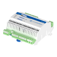
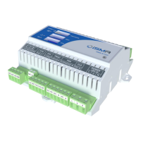
Provides detailed technical information about the iSMA-B-FCU controller.
Outlines the FCU hardware versions and configuration steps for the controller.
Configures communication protocol, baud rate, and how to restore default settings using DIP switches.
Explains how to set the controller's unique address using the MAC DIP switch.
Guides the selection between 4-pipe and 2-pipe configurations for FCU installations.
Configures the controller for single or dual stage heating operation via DIP switch.
Configures the controller for single or dual stage cooling operation via DIP switch.
Determines the control mode (digital/analog) for FCU valves and provides connection details.
Specifies the temperature sensor source and its connection for the controller.
Configures the fan type (analog, 1/2/3 speed) and its connection to the controller.
Provides a general overview of the FCU controller's inputs and outputs for connections.
Illustrates various connection scenarios for actuators and sensors in FCU installations.
| Controller Type | Fan Coil Unit Controller |
|---|---|
| Supply Voltage | 24V AC/DC |
| Digital Inputs | 4 |
| Analog Inputs | 4 |
| Analog Outputs | 2 |
| Triac Outputs | 3 |
| Operating Temperature | -20°C to +60°C |
| Mounting | DIN rail |
| Protection Class | IP20 |
| Communication Protocol | Modbus RTU |
| Outputs | 2 analog, 3 Triac |
| Communication | BACnet MS/TP |