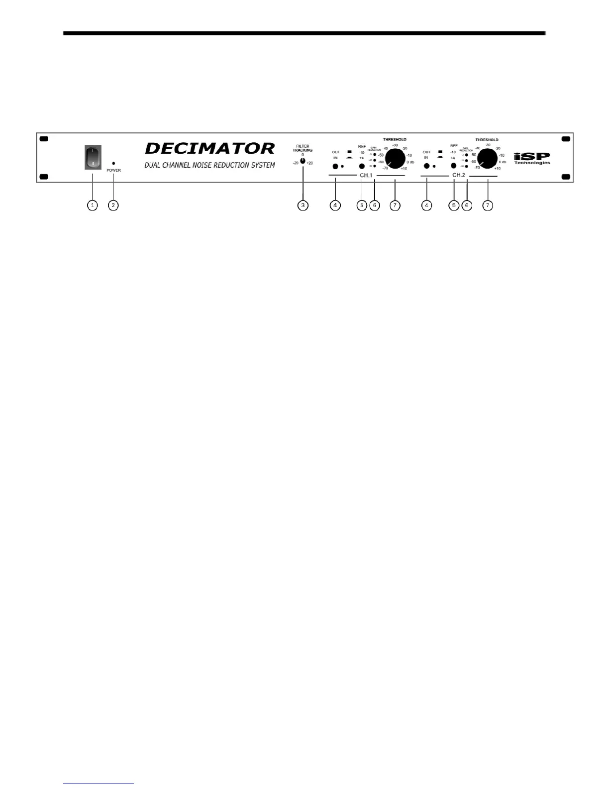
FRONT PANEL
1. POWER SWITCH
Switches the unit on and off.
2. POWER LED
Indicates when the power is on.
3. FILTER TRACKING CONTROL
This control adjusts the sensitivity of the filter threshold in relation to the downward
expander threshold. Turning this control clockwise increases the level at which the
dynamic filter opens. Turning this control counterclockwise decreases the level at
which the dynamic filter opens.
4. CHANNEL IN/OUT SWITCH AND LED
This switch is used to switch each individual channel in or out of the circuit path.
When the led is lit, the channel is active.
5. INPUT/OUTPUT REFERENCE LEVEL SWITCH
This switch changes the input and output operating reference level of each
individual channel from –10dbu when switched out, to +4dbu when switched in.
6. GAIN REDUCTION METER
This meter indicates the current amount of gain reduction (in decibels) taking place
in each channel.
7. CHANNEL THRESHOLD
This is the master threshold for each individual channel. This control is used to
adjust the threshold for both the dynamically controlled low pass filter and the low-
level downward expander. NOTE: Adjusting the
Filter Tracking
control will shift
the sensitivity of the dynamic filter in relation to the sensitivity of the downward
expander.