Via Pradazzo, 6/b
40012 Calderara di Reno
Bologna - Italy
Conservare il presente
indirizzo per future
referenze
Retain this address
for future
reference
made in Italy
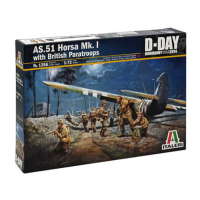
No 13561:72
scale
AS.51 Horsa Mk.I with British Paratroops
Well-know English glider able to transport more than 25 troops or a large
amount of war material and supplies in its long fuselage. It took part in
the main airborne landings of World War Two but its name is particularly
connected to the two most famous ventures of the Allied airborne troops:
the landing in Normandy and the attack to the Arnhem bridge in the
Netherlands.
EN
Notissimo aliante inglese, capace di trasportare nella lunga fusoliera oltre
25 uomini o gran quantità di materiale bellico e rifornimenti. Partecipò alle
principali operazioni di aviosbarco della Seconda Guerra Mondiale, ma il
suo nome rimane soprattutto legato alle due più famose imprese delle
truppe aviotrasportate alleate: lo sbarco in Normandia e l’attacco al ponte
di Arnhem in Olanda.
IT
Einer der bekanntesten englischen Kampfsegler, der 25 Mann oder
große Mengen Kriegsmaterial in seinem langen Rumpf befördern
konnte. Dieser Segler wurde in den bedeutenden Luftlandeunternehmen
des 2. Weltkrieges eingesetz. Besonders bekannt wurde er durch zwei
der berühmtesten Unternehmen der allierten Luftlandetruppen: der
Invasion in der Normandie und dem Angriff auf die Arnheim Brücke in
Holland.
DE
FR
Planeur anglais très connu, capable de transporter dans son long fuselage
plus de 25 hommes ou grande quantité de matériel de guerre et de
ravitaillement. Il participa aux pricipales opérations de débarquement par
avion de la Deuxième Guerre Mondiale, mais son nom reste surtout lié
aux deux plus des troupes aéroportées alliées: Normandie et l’attaque
d’Arnhem.
NL
Wellicht een der bekenste Engelse zweefvliegtuigen, met een capaciteit
van 25 man of een groot aantal materiaal. Dit zweefvliegtuig werd
ingezet bij de meeste luchtlandingsoperaties in de tweede wareldoorlog.
Bijzonder bekend werd het toesel bij de geallieerde landingen in
Normandie aan bij de aanval op de brug van Arnhem.
ES
Bien conocido planeador inglés, con capacidad para transportar 25
hombres ó gran cantidad de material de guerra y suministros en su largo
fuselaje. Tomó parte en las pricipales operaciones aerotransportadas
de a Segunda Guerra Mundial, pero su nombre está particularmente
relacionado con la dos más famosas venturas de las dos más famosas
venturas de las tropas aerotransportadas Normandía y el ataque al puente
Arnhem.
NL WAARSCHWING: Geschikt voor 14 jaar en ouder.
EN WARNING: Model for adult modellers age 14 and over
IT ATTENZIONE: Modello per collezionisti adulti di età superiore ai 14 anni
FR ATTENTION: Modèle pour modélistes de 14 and et plus.
DE ACHTUNG: Modellbausatze Für Modellbauer über 14 Jahre.
ES ATENCION: Modelo para modelistas mayors de 14 anõs.
ATTENTION - Useful advice!
Study the instructions carefully prior to assembly. Remove parts from frame with a sharp knife or a
pair of scissor and trim away excess plastic. Do not pull ol parts. Assemble the parts in numerical
sequence. Use plastlc cement ONLY and use cement sparingly to avoid damaging the model. Black
arrows indicate parts to be glued together. White arrows indicate on which frame the parts must be
assembled WITHOUT using cement. These letters (A -B - C…) indicate on which frame the parts will
be found. Paint small parts before detaching them from frame. Remove paint-where parts are to be
cemented. Crossed out parts must not be used.
ATTENZIONE - Consigli utlili!
Prima di iniziare il montaggio studiare attentamente il disegno. Staccare con molta cura i pezzi dalle
stampate, usando un taglia-balsa oppure un paio di forbici e togliere con una piccola lima o con carta
vetro fine eventuali sbavature. Mai staccare i pezzl con le mani. Montarli seguendo l’ordine delle
numerazione delle tavole. Eliminare dalla stampata il numero del pezzo appena montato facendogli
sopra una croce. Le frecce nere indicano i pezzi da incollare, le frecce bianche indicano i pezzi da
montare senza colla. Usare solo colla per polistirolo. Le lettere (A - B - C…) ai lati dei numeri indicano
la stampata ove si trova il pezzo da montare. I pezzl sbarrati da una croce non sono da utilizzare.
ACHTUNG - Ein nützlicher Rat!
Vor der Montage die Zeichnung aufmerksam studieren. Die einzeinen Montageteile mit einem Messer
oder einer Schere vom Spritzling sorfälling entfernen. Eventuelle Grate werden mit eicer Klinge oder
feinem Schmirgelpapier beseitigt. Keinesfalls die Montageteile mit den Händen entfernen. Bei der
Montage der Tafelnumerieung folgen. Pfeile zeigen die zu klebenden Teile während die weissen Pfeile
die ohne Leim zu montierenden Teile anzeigen. Bitte nur Plastikklebstoff verwenden. Die Buchstaben
(A - B - C…) neben den Nummeren zeigt,auf welchem Spritzling der zu montierende Tèil zu finden ist.
Die mit einem Kreuz markierten Teile sind nicht zu verwenden.
ATTENTION - Conseils utiles!
Avant de commencer le montage, étudier attentivement le dessin. Détacher avec beacoup de soin les morceaux
des moules en usant un massicot ou bien un pair de cisaux et couper avec une petite lame avec de papier de
vitre fin ébarbagés eventuels. Jamais détacher les morceaux avec le mains Monter les en suivant l’ordre de la
numération des tables. Eliminer de la moule le numéro de la pièce qui vient d’être montée, en le biffant avec une
croix. Les fléches noires indiquent les pièces à coller, les fléches blanches indiquent les pièces à monter sans
colle. Employer seulement de la colle pour polystirol. Les lettres (A - B - C…) aux côtés des numéros indiquent la
moule où se trouve la pièces a monter. Les pièces marquèes par une croix ne sont pas a utiliser.
OPGELET - Belangrijke bemerkingen!
Bestudeer zorgvuldig het montageplan voor het bouwen. Breek nooit onderdelen van het kader. Maak
ze los met een scherp mes of kleine nageltang. Verwijder daarna al het overtollige plastic en pas de
delen alvoorens te lijmen. Gebruik allen lijm voor plastic modellen. Werk zorgvuldig en spaarzaam,
teveel Iijm zal uw model beschadigen. Zwarte pijlen duiden de te lijmen delen aan. Witte pijlen ver-
wijzen naar bewegende delen welke niet mogen worden gelijmd. Deze letters (A - B - C…) geven de
kaders aan waarin de onderdelen zich bevinden. Schilder de kleine onderdelen voor ze van het kader
te snijden. Verwijder de verf van de te lijmen opperviakten.
ATENCION - Consejos útiles!
Estudiar las instrucciones cuidadosamente antes de comenzar el montaje. Separar las piezas de las
bandejas con un cuchillo afilado o un par de tijeras y retirar el exceso de plástico o rebada. No arrancar
las piezes. Montar las piezas en orden numérico. Utilizar SOLAMENTE pegamento para plástico y en
poca cantidad para evitar que se dane el modelo. Las flechas negras indican las piezas que se deben
pegar juntas. Las flechas blancas indican las piezas que deben ensamblarse SIN usar pegamento. Las
letras (A - B - C…) indican en que bándeja se encuentran las piezas. Pintar las piezas pequeñas antes
de separarlas de la bandeja. Retirar la pintura de los lugares por donde se deban pegar las piezas.
EN
IT
DE
FR
NL
ES
1