2
CBM-105FP1-EU1
CBM-105FN1-EU1
TECHNICAL DOCUMENTATION
Original notice - T1.3
1. Presentation of the PowerMoller product range Page 3
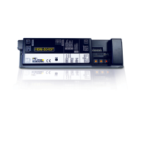
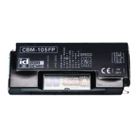
2. Presentation of the circuit board Page 4
General descritpion
Dimensions
6SHFL¿FDWLRQV
3. Technical data according motorized roller Page 6
Characteristics with motorized roller serie PM500FE
Characteristics with motorized roller serie PM605FE
Characteristics with motorized roller serie PM500FP
4. Location of items Page 16
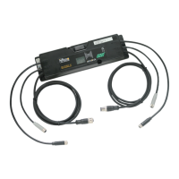
5. Wiring Page 16
Schema
Connector CN1 - Supply 24 VDC
Connector CN2 - Terminal 1 : Start / Stop (RUN)
Connector CN2 - Terminal 2 : Direction of rotation CW/CCW (DIR)
Connector CN2 - Terminal 3 : Speed variation (V-IN)
Connector CN2 - Terminal 4 : Error signal (ERR)
Connector CN2 - Terminal 5 : Impulse signal (PLS)
Connector CN3 - Motor connector
6. LED 1 et LED 2 Page 21
7. Potentiometers VR1 (acceleration) et VR2 (deceleration) Page 21
'LSVZLWFKHVFRQ¿JXUDWLRQ6: 3DJH
Dip-switch 1 : Selection speed range
Dip-switch 2 : Selection internal / external speed
Dip-switch 3 : Selection direction of rotation
Dip-switch 4 : Error signal
Dip-switch 5 : Activation / deactivation of brake servo
Dip-switch 6 : Selection logic error signal NPN / PNP
6:VHOHFWLRQ¿[HGVSHHG 3DJH
Annex 1 : Declaration of incorporation Page 28
SUMMARY
 Loading...