www.ittcontrols.com contact@ittcontrols.com
9
Model 227A Dierential Pressure Indicator Section 3
Section 3—Maintenance and Calibration
For preventive maintenance, periodically inspect linkage for wear.
When repairs are necesssary, review this section for maintenance procedures
such as bezel/lens installation and removal, scale plate installation and re-
moval, pointer installation and removal, and indicator calibration.
IMPORTANT: See Appendix A for related warning/caution notices and instructions
on DPU inspection, cleaning, service, repair, range change, and BUA
replacement. Never perform maintenance/repair on the instrument
or DPU without
reviewing all procedures and warning/caution
notices in Appendix A.
Tools
The following tools are recommended for general maintenance of the Model
227A DP indicating switch.
Table 3.1—Tools
Equipment Purpose
Pointer Puller Pointer removal
Small Screwdriver Scale plate removal and replacement
Medium Screwdriver Bezel removal and replacement
1/4" and 1/8" Open-end Wrenches Zero (1/4") and Range (1/8") adjustments
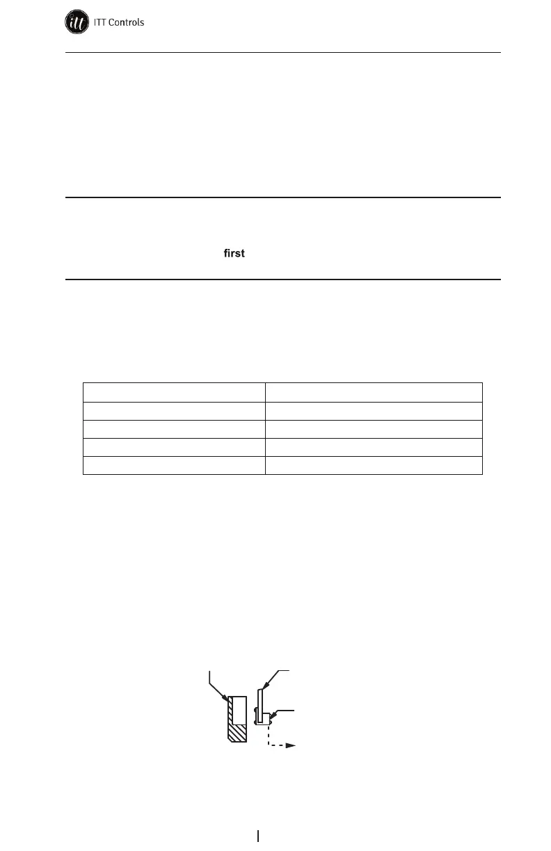
Bezel/Lens (or Cover) Installation and Removal
To remove the bezel and lens (or cover), perform the following steps.
1. Loosen the three screws on the front of bezel (Figure 3.1).
2. Tilt the bottom of the bezel and slide the bezel upward.
To reinstall the bezel and lens, assemble the components per Figure 3.1. The
two snubbers (Part No. 9A-C0266-0028C) on the scale plate should not be
compressed against the lens cover and the pointer should not touch the lens.
(9A-C0277-0029C)
Cover (Lens)
(9A-C0181-0038C)
Gasket
(9A-C0277-0026C)
Case
Figure 3.1—Bezel and lens cover



 To Next Page