This document serves as a workshop manual for Flygt mixer models 4610 and 4620, covering both standard and specially approved (Ex) versions. It provides detailed instructions for dismantling and assembling the mixers for repair and reconditioning, along with essential safety precautions, technical data, and exploded views of the components.
Function Description
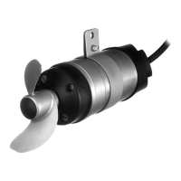
The Flygt 4610 and 4620 mixers are designed for various applications, likely involving the mixing of liquids, slurries, or sewage in industrial or municipal settings. The manual details the internal components, including the motor (stator and rotor), propeller, bearing assembly, and sealing systems, which work in conjunction to achieve the mixing function. The "Specially approved versions (Ex)" indicate that these mixers are designed for use in potentially explosive atmospheres, incorporating flameproof features to prevent ignition of surrounding gases or dust. This involves precise control over joint widths and gaps to contain any internal sparks or explosions.
Important Technical Specifications
The manual provides critical technical data for the 4610 and 4620 models:
- Standard Versions:
- Specially Approved Versions (Ex):
- 4610.490: EEx d IIB T4 (European Norm, ATEX Directive) and FM: Class I Div.1 Grp. C and D (Factory Mutual)
- 4620.490: Class II Div 1 Grp. E, F and G, Class III Div. 1 (Factory Mutual)
- Winding Resistances (at 20°C / 68°F):
- 3 Phase (50 Hz / 60 Hz):
- Stator No 640 67 01: 12.6 Ohm/Phase (50 Hz), 9 Ohm/Phase (60 Hz)
- Stator No 640 67 02: 15.4 Ohm/Phase (50 Hz), 7.3 Ohm/Phase (60 Hz)
- Stator No 640 67 03: 19.7 Ohm/Phase (50 Hz), 19 Ohm/Phase (60 Hz)
- Stator No 640 67 04: 42.5 Ohm/Phase (50 Hz)
- Stator No 640 67 05: 3.15 Ohm/Phase (50 Hz)
- Stator No 640 67 06: 11 Ohm/Phase (60 Hz)
- Stator No 640 67 07: 21 Ohm/Phase (60 Hz)
- Stator No 64068 01: 6.91 Ohm/Phase (50 Hz), 6.91 Ohm/Phase (60 Hz)
- Stator No 64068 02: 8.62 Ohm/Phase (50 Hz)
- Stator No 64068 03: 10.7 Ohm/Phase (50 Hz), 10.7 Ohm/Phase (60 Hz)
- Stator No 64068 04: 21.2 Ohm/Phase (50 Hz)
- Stator No 64068 05: 1.72 Ohm/Phase (50 Hz)
- Stator No 64068 06: 4.73 Ohm/Phase (60 Hz)
- Stator No 64068 07: 1.29 Ohm/Phase (60 Hz)
- 1 Phase (50 Hz / 60 Hz):
- Stator No 64072 01: 4.58 (main phase), 7.87 (auxiliary phase) (50 Hz)
- Stator No 64072 02: 3.37 (main phase), 6.02 (auxiliary phase) (50 Hz)
- Stator No 64072 03: 1.15 (main phase), 1.97 (auxiliary phase) (50 Hz)
- Stator No 64072 04: 3.06 (main phase), 5.20 (auxiliary phase) (60 Hz)
- Stator No 64072 05: 2.30 (main phase), 4.00 (auxiliary phase) (60 Hz)
- Stator No 64072 06: 0.764 (main phase), 1.30 (auxiliary phase) (60 Hz)
- Lubricants:
- Part No 90 17 52: Oil (Mobil Whiterex 309)
- Part No 90 18 00: Oil (Castrol iloform BWN 205)
- Seal Tightness Check: Applied pressure should be 0.5 bar (max 1 bar). Maximum allowed pressure drop (ΔPmax) is calculated as 0.017 * Po * t/V [bar], where Po is pressure in test object, t is test time [min], and V is volume of test object [lit].
- Monitoring Equipment: Three normally closed thermal contacts in the stator, rated for max 250 volts, breaking 5 amps max, rated 1.6 cosφ=0.6, or 2.5 cosφ=1.
- Flameproof Gaps (for Ex versions): Detailed table with joint lengths, diameters, and allowed gap ranges (min/max) for various components, crucial for explosion protection.
Usage Features
The manual focuses on maintenance and repair rather than operational usage. However, it implicitly highlights features related to the mixer's design for serviceability:
- Modular Design: The mixer appears to be constructed from several distinct units (oil housing, bearing cover, entrance flange, connection housing, shaft-rotor unit), facilitating individual component replacement and repair.
- Clear Identification: Data plates provide comprehensive information including serial number, product code, curve/propeller code, country of origin, electrical specifications (phase, voltage, current, frequency), thermal protection, duty class, and ambient temperature, which are essential for correct application and servicing.
- Ex-Proof Features: For specially approved mixers, strict dimensional accuracy and surface finish requirements for flamepaths are critical for safe operation in hazardous environments. The design incorporates specific joint types and tolerances to prevent flame propagation.
Maintenance Features
The workshop manual is primarily a maintenance guide, detailing a step-by-step process for servicing the mixer:
- Dismantling and Assembly Procedures: Comprehensive instructions with illustrations cover the removal and installation of components such as the jet ring, guiding claw unit, propeller, oil housing, plug-in seal, bearing cover, spring, entrance flange, entrance cover, connection housing, cable, shaft-rotor unit, and bearings.
- Tooling: A list of specific tools is provided, including screwdrivers, hexagon socket wrenches, torque wrenches, circlip pliers, pullers, bearing mounting sets, club, knife, stripping tongs, pliers, funnel, oil tray, screw vice, and drifts. Special tools are highlighted for specific tasks.
- Safety Precautions: Emphasizes disconnecting power, securing the machine, using appropriate lifting equipment, observing health hazards, and following local safety regulations. For Ex-approved mixers, only authorized personnel should perform repairs, and strict adherence to dimensional checks and genuine spare parts is mandatory.
- Seal Tightness Check: A procedure to verify the integrity of the oil housing seal, including oil draining and pressure testing.
- Oil Filling: Instructions for filling the oil housing with specified lubricants (Mobil Whiterex 309 or Castrol iloform BWN 205) and tightening inspection/oil screws to a specified torque (10 Nm/7.4 ft.lb).
- Cable Connection: Detailed wire diagrams for 3-phase (Y and Δ) and 1-phase configurations, including connection of stator leads and cable leads. A critical safety note emphasizes that the earth lead must be longer than phase leads to ensure it is the last to disconnect.
- Bearing Installation: Specific instructions for fitting bearings using appropriate tools (SKF B20-52, SKF A12-37, or tubes of specified diameters) and ensuring correct orientation and seating.
- Component Inspection: Guidelines for inspecting joint surfaces for scratches, tool marks, corrosion, blow holes, or hairline cracks, especially for Ex-approved versions, where such defects can compromise safety.
- Post-Repair Testing: For Ex-approved mixers, insulation testing and test-running are required after assembly to ensure compliance and functionality.
- Documentation: The importance of recording all findings, measurements, and details of repair work, particularly for Ex-approved products, is stressed.