EOMs Operating Manual
Ref. Ed. 0 – 08/02/2021 12
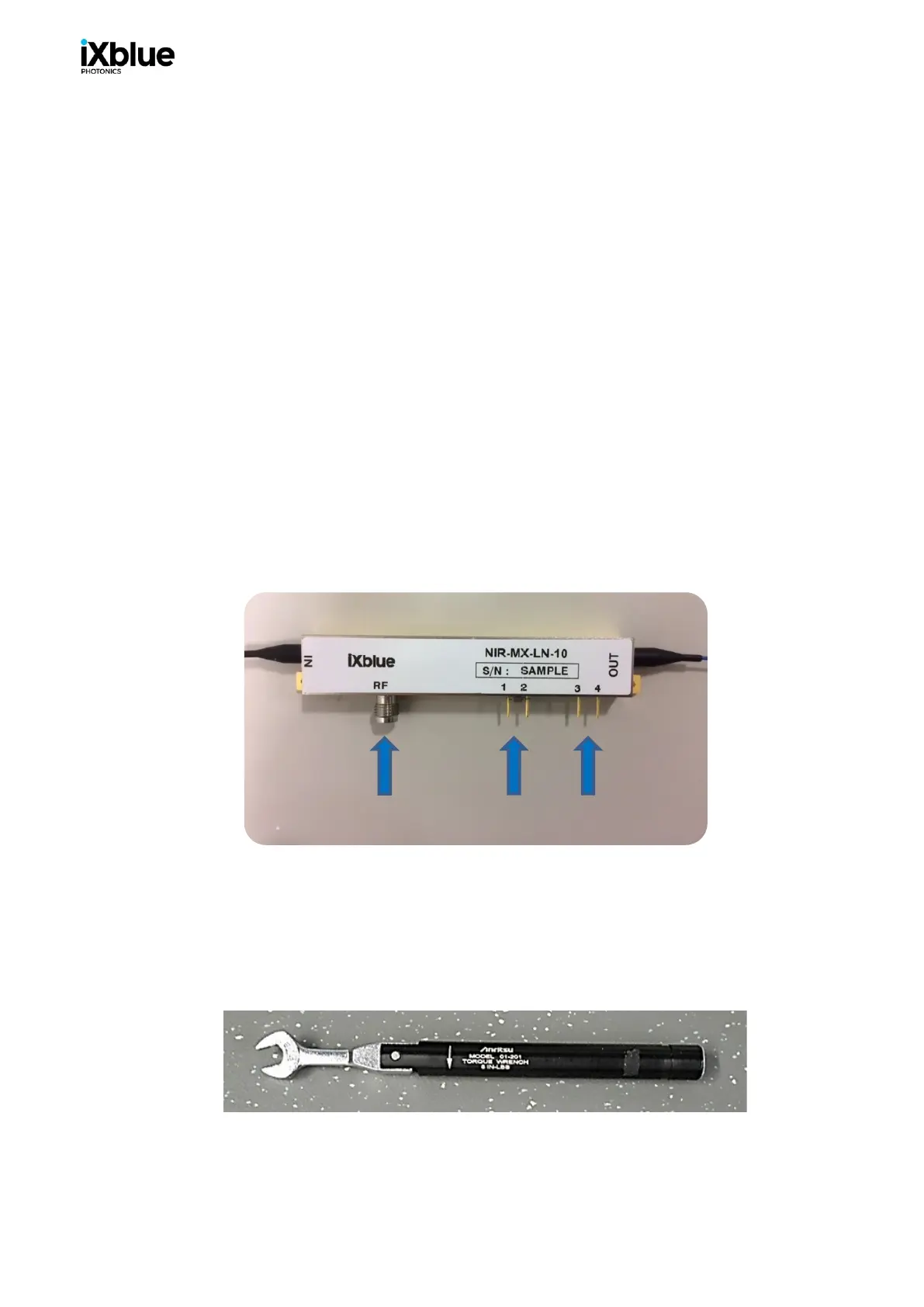
2.1 Electrical interfaces
The iXblue Photonics modulator comes with three kinds of electrical ports:
1) RF port: where the modulating signal is applied. Depending on the frequency range of
application, three kinds of RF/microwave connectors are used:
• 2.92 mm / K type, female, compatible to mate with SMA / 3.5 mm connectors.
• 2.4 mm, female, compatible to mate with V / 1.85 mm connectors.
• 1.85 mm / V type, female RF/microwave coaxial connector.
2) DC port: where a DC bias is applied to set the operating point of the intensity modulator.
The DC connectors are gold plated pins ( 0.76 mm).
3) Internal photodiode (PD) port: only used with intensity or IQ modulators. The connectors
are gold plated pins ( 0.76 mm).
Fig. 17
2.1.1 RF CONNECTOR
• RF inputs must be connected with SMA rigid coax. @ 0.8 Nm ≤ Torque ≤ 1.2 Nm
Fig. 18