Please read these instructions completely before commencing installation
1. Inspect the heater for damage before proceeding with installation.
2. All models must be installed by a registered electrician.
3. Ensure an isolating switch is incorporated in supply wiring, and that this switch isolates all live
connections to the heater.
4. Unit must be installed in accordance with Wiring Rules AS/NZS 3000:2000.
Installation
Poor
Good
Good
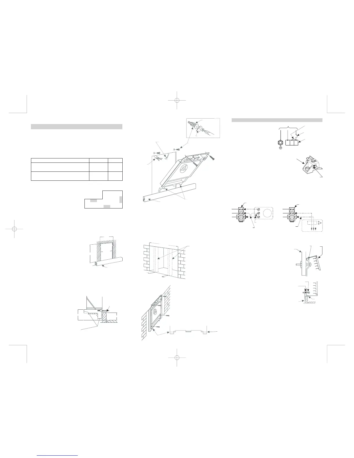
Locating the heater
Chose a location to give good distribution of warm air
through the room. Avoid corners to allow spread of warm
air (see Fig.1) Do not install close to or directly opposite
furniture,or nearcurtainsor drapes.
Electrical supply requirements:
Removetwo screwsinlowergrille.
Using screwdriver through slots in top of front panel,
remove jacknuts and discard angle from two screws
securingfront totopof heater.Check thatfan spinsfreely.
To remove front
Min.Distance betweenstuds393 mm(15 “)(see Fig.2).
Min. depth of stud plus one thickness of wall cladding 88
mm(3 ½").
½
Top ofskirting should beno lessthan 60 mm(2 ¼")and no
morethan 100mm(4")above floorcovering(see Fig.3).
Breakplasterboard awayfrombehind skirtingboard.
Fig. 3
Cavity preparation:
Installation in a stud wall
Clearance between underside of heater surround and top of floor covering must not be less than 65 mm
(2 “)- seeFig 3.½
Important
It is important that a clearance of at least 6
mm (¼") be maintained between the back, side
and top surfaces of the heater rear box ( and
back vent stub if fitted) and the wall cavity into
which it is fitted.
Stand -off spacers are incorporated in the design
to indicate the clearances required.
Clearances
Additionally 25mm (1") to be maintained
between these surfaces and any adjacent
material
415mm
393mm
Skirting board
625mm
Tongues
65 mm min
60 - 100 mm
Thermostat wires
Jacknuts
To set jacknut drill 9.5mm (3/8“) diameter hole in wall
cladding. Push jacknut into hole. Pass metal thread screw
through friction wrench and into jacknut. Hold friction
wrench against jacknut and tighten screw, remove screw,
jacknutremains captive(seeFig.4)
Tongues
Skirting board
Friction wrench
Jacknut in wall
Installation in brick chimney
Cut
832 mm max.
415mm apart
Dummy studs
if required
583 mm min
665 mm max
411 mm min.
If necessary, cut off
2 tabs as shown
Drill flanges and attach screws as required
External wiring:
Isolating switch to be installed in accordance
withclause 4.3.53 ofAS/NZS3000:2000.
A circuit breaker is accepted as an isolating
switch(see Fig.8).
.
Note: For 2 phase supply remove
bridge between A1 and A2
For thermostat location and installation please refer to thermostat Installation Instructions supplied
withthe thermostat.
For thermostat connection to the thermostat terminal block refer to Fig. 10 (for Models 10634, 10636,
1074and 1076)or toFig. 11forModel 10646. Recommendedwire 1.0mm T.P.S.
2
Thermostat location and installation
Please leave Operation Instructions and Warranty with heater or hand to householder.
Mr INSTALLER
To check operationset thermostat to asetting higher than roomtemperature and select "LO" and"ON".
Thefan onlowspeed andone heating element should operate.
Then select "HI", the second elementshould beenergized andfan willrun onhigh speed,giving fasterair
flowand higheroutlettemperature.
NOTE:When ON/OFFswitchisON, neonglowscontinuously oneitherLO orHI setting.
Check that unit functions
Fix front to heater through lower grille with 2 long
metal thread screws, using serrated lock washers.
Tightenall 4screws (seeFig. 12and13).
Discardplastic filmfrom decaland switches.
Hook front of heater over lip on upper edge of
heater, making sure switches and decal do not
catchon apertureedge.
Pushtop fullydown (seeFig. 12).
To fit front to heater
A1 9.5A
A2 9.5A
A1 12.5A
A2 12.5A
A1 19A
A1 25A
240/230 V 50 Hz
Two phase*
Single phase
The terminal block is completed with clamp plate. Please make
sure that wire enters terminal block above the clamp plate (see
Fig.9). Nocontact willbemade ifwire entersbelow clampplate.
Important
For additional information or name of your nearest agent please phone (03) 5222 2922
Electric cable
HotlineModel 10174and10176 only.
Cap off chimney to prevent rain entry. Allow some ventilation to prevent dampness. Fix to brick or
alternativelyprovide dummystuds.
Model No.s 10174 and 10634 4.5kW 19A
Model No.s 10176, 10636 & 10646 6kW 25A
*NOTE: For 2 phase supply remove bridge between A1 and A2 (see Fig. 8).
Fig. 2
Fig. 1
Fig.4
Fig. 5.
Fig. 7
Fig. 6
Lower flangeof heaterbehind skirting. Tongues rest ontop ofskirting board(see Fig.5). Make electrical
connectionsand tightenALLterminals.
Fixto wallas indicated,engaging two topscrews intojacknutsbut donotfully tightenat thisstage.
To attach heater’s body to wall
Fig. 9
Wallboard
Top edge
of heater
Heater
front
Fig. 12
Skirting board
Rubber
Retaining
Ring
Serratted washer
Tongues
Fig. 13
Connection of thermostat to heater
Model 10646 - Classic with timer
Fig. 11
From thermostat through
hole between relay and
switch bracket
A
B
C
with 2A fuse
Thermostat terminal block
NOTE: Thermostat circuit is protected by 2A fuse which is inserted into the thermostat terminal block fuse
holder.
White
Red
Blue
2A
CLAMP PLATE
NA2A1
Earth
Isolating switch
Connection of power supply for single phase
Power terminal block
Bridge
Fig. 8
Power terminal block
Power supply
Connection of thermostat to heaters
Model No: 10174, 10634, 1063610176,
White
Red
Blue
Capacitor
From thermostat through
hole between relay and
switch bracket
2
1
3
Fig. 10
2A
with 2A fuse
Thermostat terminal block
 Loading...