Do you have a question about the J.A. Woollam M-2000 and is the answer not in the manual?
Explains the three types of message boxes used in the manual for warnings, cautions, and notes.
Provides essential safety guidelines for operating the equipment safely and as intended.
Specifies the recommended temperature and humidity conditions for optimal equipment operation.
Details the different M-2000 models and their spectral ranges and lamp types.
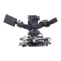
Describes the various parts that make up the M-2000 ellipsometer system.
Details the different types of light sources used in the M-2000 system (XLS-200, FLS-860, FQTH-100).
Describes the different receiver units available for the M-2000 system (MQD-Single, MQD-Dual).
Explains the function of the module controlling detectors and lamps, including the spectrometer.
Details the EC module's role in system control, communication, and embedded computer functions.
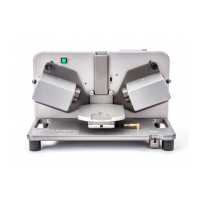
Describes the auto-angle base unit and its variations based on mapping stage size.
Explains the optional power control module for system power management and emergency shutdown.
Provides a step-by-step guide for assembling the ellipsometer system, including preliminary steps.
Explains the procedures for connecting the system's AC power through surge suppressors.
Provides guidance on connecting various cables between system components using the cabling diagram.
Covers setup of the computer, rack mount table option, and system enclosure.
Guides the user through configuring the EC module's TCP/IP settings for system operation.
Outlines the steps for setting up the operator's computer, including software and network configuration.
Covers USB camera setup, driver installation, and setting the system to High Performance Mode.
Step-by-step instructions for powering on the M-2000 system components in the correct sequence.
Covers manual system and sample alignment processes, including tip/tilt adjustments.
Details automated system and sample alignment procedures using the optional automated tip/tilt feature.
Describes how to perform a system check and calibration using a reference wafer.
Provides instructions for safely shutting down the computer, monitor, and system components.
Explains the process of collecting ellipsometric data from a sample using the CompleteEASE software.
Describes how to use and create recipes for automating measurements and analysis.
Explains different data types for acquisition (Standard, Mueller Matrix, Reflection Intensity).
Details how to set up and perform routine tests for system performance monitoring.
Introduces the optional focusing optics, their function, and adjustment screws.
Provides step-by-step instructions for installing the focusing optics probes.
Explains how to perform lens correction to account for Delta Offsets introduced by focusing lenses.
Guides sample alignment and system check when using focusing optics, emphasizing Z-height.
Details data acquisition procedures when focusing optics are installed, noting Z-alignment needs.
Instructions for safely removing the focusing optics probes from the system.
Introduces the controls and general operation of the automated translation stage.
Explains how to create and use scan patterns for automated sample mapping.
Covers defining substrate dimensions, points, and fill methods for scan patterns.
Guides testing scan patterns, setting alignment, and saving scan patterns for recipes.
Describes the optional sample rotation stage and its use in measurements.
Details how to correct for wobble when using the rotator stage for accurate measurements.
Explains how to mark the beam position for accurate camera alignment.
Guides the process of calibrating the camera's field of view for accurate imaging.
Describes how to configure and activate the in situ mode for process chamber measurements.
Procedures for replacing and aligning D2, Xe, and QTH lamps in different M-2000 models.
Covers safe disposal of arc lamps and replacement of the reflective mirror in the light source.
Instructions for optical fiber adjustment for light throughput and general system cleaning.
Verifies instrument operation by measuring a calibration wafer and air.
Describes an alternative method to verify instrument operation and calibration status.
Emphasizes the importance of correct sample alignment for accurate measurement data.
Explains how to monitor and adjust lamp intensity and detector signal.
Outlines steps to verify system alignment integrity, especially after component changes.
Details how to correct for systematic offsets in angle values of the opto-mechanical system.
Explains the procedure for calibrating wavelengths and compensator coefficients.
Covers general troubleshooting steps, checking LEDs, and creating debug files for support.
Lists and explains common error messages like Phase Sensor, Polarizer Homing, and Spectrometer errors.
Addresses common operational issues such as alignment sensitivity and motor not turning.
Troubleshoots software initialization, calibration fit, and signal screen problems.
Diagnoses and resolves issues related to lamps, light sources, and USB cameras.
Lists specifications for EC Module, power supplies, computer, monitor, and surge suppressors.
Specifies the recommended temperature and humidity for optimal equipment operation.
| Software | CompleteEASE |
|---|---|
| Category | Spectroscopic Ellipsometer |
| Angle of Incidence | Variable |
| Measurement Type | Spectroscopic Ellipsometry |
| Angle of Incidence Range | 45° to 90° |
| Measurement Speed | Fast |
| Detector Type | CCD or InGaAs, depending on model |
| Sample Size | Up to 200 mm in diameter |
| Beam Diameter | Approximately 2 mm |