MAN0062
2
J-TEC Associates, Inc.
Revision G
Note: Not approved for measuring explosive gas mixtures except crankcase vapors.
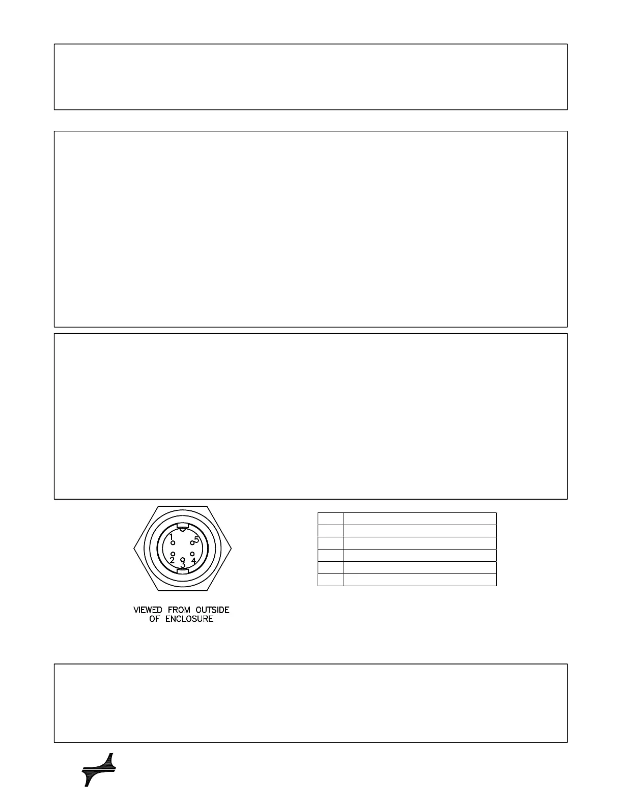
FIGURE A
Flowmeter Connector Pin-Outs
Pin
Description
1 Power Ground
2 Signal Ground
3 Output (0-5 VDC or Frequency)
4 Power Input (+12 to +24 VDC)
5 Not Used
Introduction
J-TEC flowmeters operate on the principle of vortex shedding. A small strut inside the flow tube creates a
Karman vortex street and the vortex formation is sensed by means of an ultrasonic beam directed across the
tube. The flowmeter electronics uses the vortex frequency to determine the flow rate. J-TEC flowmeters have
Mechanical Installation
The flowmeter has been shipped completely assembled and tested. It is ready to install and operate. The
labeling of the flow direction on the flowmeter must be aligned with the flow in the pipe.
The flowmeter should be installed with a minimum of 20 pipe diameters of straight pipe upstream and 10 pipe
diameters downstream from the flowmeter. For example, a one-inch tube or hose should have 20 inches of
straight length immediately before the flowmeter inlet tube. This condition provides a more symmetrical flow
profile, which is necessary to obtain accurate and repeatable results.
A typical connection to the flowmeter is made by placing a customer supplied flexible hose onto the outside of
the inlet tube and outlet tube.
If liquids are present in the gas flow stream, the flowmeter should be installed so that liquids will not collect on
the ultrasonic transducers housed beneath the flow direction indicators. Installing the flowmeter vertical with
flow into the top and out the bottom will encourage liquids to drain out of the flowmeter.
An optional filter canister or buffer chamber placed in the pipe, between the crankcase and the flowmeter, will
minimize the effect of pulsating flows, and collect oil and water droplets to keep the flowmeter cleaner. The
buffer should be sized for minimal pressure loss. Contact J-TEC for ordering information.
Cleaning and Maintenance
The inside of the flow tube and strut must be kept clean. If the meter produces erratic readings a cleaning
schedule should be implemented. To clean the flow tube and strut, gently brush the inside of the tube with a
soft brush or cotton swab. A mild detergent and water solution may be used to loosen deposits. Ensure the
flowmeter is completely dry before use.
DO NOT use wire brushes or high-pressure liquids. These may cause damage to the transducers.
Electrical Installation
A filtered power supply must provide at least 35 mA at +12 to +24 Volts Direct Current (VDC).
Analog output signal is 0 to 5 volts DC, proportional to the flow range. (Output impedance is 100 ohms).
Optional output of 0 to 10 volts or 1 to 10 volts available.
Optional output of frequency/pulse is also available. Pulse output is 0-10V peak, open drain FET.
Cable length is limited to 50 feet.
A customer supplied four-conductor cable made of 26-22 AWG wire is required to make connections to the
flowmeter.
The contact pins, of the flowmeter connector, are identified in Figure A. The supplied mating connector which
connects to the flowmeter, requires customer assembly. The mating connector is CONXALL part number
6282-5SG-519 (J-TEC part number DRJ0735).
 Loading...