EasyManua.ls Logo

JABSCO 62040-4 Series User Manual

JABSCO 62040-4 Series
4 pages
To Next Page IconTo Next Page
Page #1 background imageLoading...
Page #1 background image
FEATURES
Complete drive unit enclosed in light housing.
Single control lever for vertical and horizontal
movement.
Dual speed control for precise beam movement.
On-off Spot only on 7" and 8"models.
Exclusive Clutch-A-Matic feature protects drive unit
against overload. Can operate for extended periods
against limit stops without harm. Light head may be
moved manually without damage to the drive unit.
Internal brake system holds beam firmly on target.
Includes control with on-off, dual speed control,
and single control for vertical and horizontal
movement.
bluBledoM Candlepower
Number Volts Head Base Type (Combined)
62040-4002 12 Brass Brass 7" Spot 230,000
62040-4006 24 Brass Brass 7" Spot 230,000
62042-4006 24 Brass Brass 8" Spot 500,000
CABLE LISTING
Part Number Description
43990-0013 10' Cable Assembly
43990-0014 15' Cable Assembly
43990-0015 25' Cable Assembly
43990-0016 35' Cable Assembly
67294-0000 50' Bulk Cable
CONTROLS
Part Number Description
43670-0003 Primary Control 12 V
43670-0004 Secondary Control Kit 12 V
60070-0000 Primary Control 24 V
18753-0335 Secondary Control Kit 24 V
7” & 8” ELECTRIC REMOTE
CONTROL SEARCHLIGHTS
Models 62040-4 Series
62042-4 Series
Models 62040-4 Series
& 62042-4 Series
Question and Answer IconNeed help?

Do you have a question about the JABSCO 62040-4 Series and is the answer not in the manual?

JABSCO 62040-4 Series Specifications

General IconGeneral
BrandJABSCO
Model62040-4 Series
CategoryLighting Equipment
LanguageEnglish

Summary

7" & 8" ELECTRIC REMOTE CONTROL SEARCHLIGHTS

FEATURES

Key attributes include enclosed drive, single control lever, dual speed, Clutch-A-Matic, and internal brake system.

INSTALLATION AND OPERATION

LIGHT MOUNTING

Instructions for mounting the searchlight base and feeding the wiring cable through the mounting surface.

CONTROL MOUNTING

Details mounting the control unit on various panels, including hole size, wiring, and sealing.

CIRCUIT PROTECTION

Explains the two fuses (10A for bulb, 3A for motor) protecting the unit's circuits.

OPTIONAL SECONDARY CONTROL MOUNTING

Covers installing a secondary control station, including panel cutouts and cable routing.

TROUBLESHOOTING

EXPLODED VIEW AND MAINTENANCE

BULB REPLACEMENT

Instructions for replacing the bulb, including wire connections and securing the retaining ring.
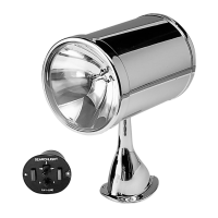
WIRING AND DIMENSIONS