5
General Information
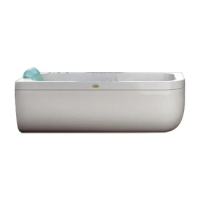
Most of the Jacuzzi® whirlpool baths are available with the back-
rest on either the left or right-hand side. The Left-Right version
can be identied by standing in front of the bath, opposite the
control panel.
Jacuzzi Europe S.p.A. recommends the use of the removable
front panel, available on request (but supplied as standard
equipment with several models) which allows easy access for
any necessary maintenance. On request, side panels for one or
both of the short sides can be supplied (excluding corner mod-
els). Panels are not available for tted baths.
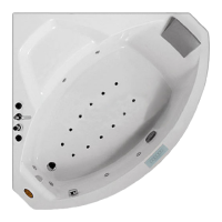
In the corner models, a gap about 50 cm wide is left along the
entire external border of the bath to allow the assembly and re-
moval of the panels.
For tted baths, or those with the control panel facing the wall,
access to the electric pump, electrical box and the area below
the control panel must be provided for maintenance purposes.
This access space can be closed with removable panels (see
specication sheet, ref. 6, 6a, 6b, 6c) at least 45cm high, meas-
ured from the oor. Furthermore, adequate ventilation must be
available for the bath unit, with vents between the bath covers
and the removable panels, well distributed and non-obstructed.
We recommend installing the bathtubs to already tiled or laid
walls and ooring, where the space available between the bath-
tub base and the oor itself allows for the attachment of si-
phons/siphon boxes of suitable dimensions (with the exception
of some models). Make sure that the oor drainage hole (ref. 1)
is correctly positioned for the bath drain, shown in the specica-
tion sheet (dimension Y), depending on the type of siphon to be
used (not supplied).
For the Aquasoul, J-Sha, Sharp and Maxima models, an
excavation must be provided in the oor for positioning
the siphon (see respective specication sheet).
All models need to have the electrical box, xed to the frame (ref. 2),
connected to the electrical supply and correctly earthed. The cable
may follow various routes as long as there are no free-hanging con-
nections. In all cases, refer to the ”Electrical safety” chapter.
It is recommended to prepare the electrical power supply with
one single-phase line (voltage between phase and neutral:
220-240V).
The device can be powered with a double phase line, providing
that the voltage between phases is 220-240V.
CAUTION: For the models equipped with heater, make
certain that the building's electrical system is capable
of delivering the required power (see respective speci-
cation sheet) and that it is appropriately sized.
Some models provide for installation of a oor lighting
system; refer to the respective pre-installation instructions
(ref. 2 bis).
Hot/cold water preinstallation
CAUTION: IEC 603351/A2 The pressure of the water
system supplying water to the appliance must not ex-
ceed 600 kPa (6 bar).
- models without brassware
The water can be supplied from an external tank unit with a wall
outlet (minimum length X), positioned at references 3 or 3a in-
dicated in the specication sheet. Position 3b can be used only
when the drain is against the wall.
Some models without brassware are also available with a drain-
age outlet with spout.
In this case it is possible to use two tted taps or a single con-
trol tap (not recommended for high capacity baths, given the lower
ow rate of the latter) using the water supply coming from the
drain column with supply jet.
It will, however, be necessary to install a specic DB-type
protection unit (standard EN 1717), located at least 15cm
above the edge of the bath. Concerning system methods, we
recommend you contact your water company and/or your
plumber.
The water pipe (copper, 14mm ø) for the mixed water can come
up from the oor, in the position indicated by the symbol * in the
plan drawing (ref. 4). Other positions can be used for the outlet
of the pipe (see 4a), taking into consideration that the pipe must
reach the upper part of the drain column.
If a bath unit is used without a shower diverter, it will be neces-
sary to t a diverter after the taps to allow the future installation
of a shower head.
- models with brassware
It is recommended that the outlet for the two 14mm (or 1/2") ø
copper pipes for hot and cold water be positioned on the oor in
the location marked with the symbol * in the plan drawing (ref. 5).
Other positions can be used for the outlet of the pipes, taking into
consideration that they will have to be connected to the tap inlets.
It is recommended that these double cone junctions are of a suf-
ciently small diameter.
Note for the GEMINI/GEMINI CORNER models: these
baths are equipped with two independent tap ttings;
thus two 1/2” hot-cold water supplies will have to be pro-
vided (ref. 5-1 and 5-2). Alternatively, it is possible to pro-
vide a 3/4” water supply (to guarantee the overall ow rate)
and then divert 1/2” piping for the two tap ttings.
J-Sha models
For these models, the electricity, drainage and hot/cold water
connections must be provided following the indications given
for models with tap ttings.
5