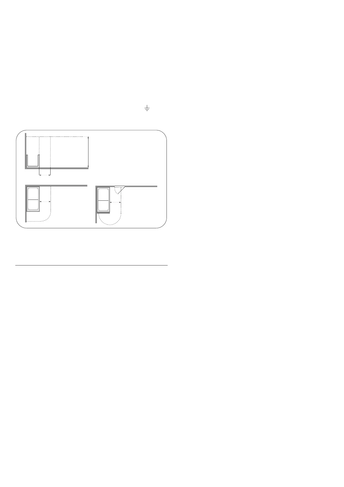
the legal requirements and regulations for each country. In particu-
lar, no electrical installations are to be made within the area sur-
rounding the whirlpool bath in a range of 60 cm horizontally and
225 cm vertically. Connection to the electrical system of the build-
ing must be made using a sheathed cable with characteristics not
inferior to H 05 VV-F 3x2,5 mm
2
.
”Young Collection” Jacuzzi
®
whirlpool baths must be con-
nected to an electrical supply fitted with a 0.03A differen-
tial switch.
”Young Collection” Jacuzzi
®
whirlpool baths are fitted with a termi-
nal, located near the pump and labelled with the symbol , for the
equipotential connection of the surrounding metal components, as
required by regulations EN 60335.2.60.
ASSEMBLING THE TAPS AND FITTINGS
(if included)
(
5) ATTENTION: the position of the water outlet varies
depending on the type of tub.
Take the box that holds the various components of the taps
and fittings.
NOTE: assembly of the taps and fittings must be done
with the tub outside of the place of installation and be-
fore it is fastened to the floor.
(
6) (1) Unscrew the headless screw. Slide out the cylin-
der of the tub filler (2); (3) then tighten ring nut “A” and ring
nut “B”, and finally install the gasket “C”.
NOTE: keep the headless screw.
(
7) From under the tub edge, insert the cylinder in the in-
dicated hole and tighten the coupling from above with the o-rings.
(
8) (1) By means of the coupling and the ring nut (2), tem-
porarily fasten the cylinder, ensuring that it is parallel with the
tub edge (3).
(
9) Install on a tap the same units used for the cross
cylinder. Repeat the operation for the other tap.
(
10) From under the tub edge, insert the taps in the in-
dicated holes and tighten from above the ring nuts with the
o-rings
(
11) By means of the respective ring nuts temporarily fas-
ten the taps, turning one with respect to the other, so as to
make it easier to install the flexible hoses (3).
(
12) (1) Install the covers as shown, and fasten them
from above using the ring nuts (2).
(
13) Install the shower support by placing the indicated
gasket.
(
13) From beneath the tub edge, apply another gasket and
attach it with the indicated nut.
(
14) Take shower hose (fittings 1/2”-3/8”) and insert them
in the following components (from the side of the 3/8” fitting):
button E - ring nut F - rosette G - threaded tube H - Teflon
washer I (internal ø 23,3 mm) - threaded tube J - spring K
- Teflon washer L (internal ø 26 mm) - gasket M (the brass
part must face downwards)
(
15) Fasten the flexible hose of 1/2” M-F (provided) to
the cross cylinder and run it through the inside of the show-
er support, placing it over the tub edge.
(
16) (1) From above the tub edge, connect the shower
hose to the hose you just installed, placing the gasket. (2) Line
up washer L and gasket M inside the shower support.
(
17) Screw the threaded tube J all the way into the show-
er support.
(
18) (1) Tighten washer I onto threaded tube H and place
the latter on spring K inside the threaded tube J (2).
(
19) Place rosette G in contact with the tub. Then screw
on ring nut F and finally button E on the threaded tube H.
(
20) Run the flexible hose under the tub edge and screw in
the shower head, placing the gasket.
Use of the shower head
(
20) To remove the shower head from its support, press the
ring nut down (1) and turn it about 45° (2), in order to release
the hose.
After use, put the shower head back in place, press the ring nut
and turn it about 45°.
(
21) Press the water supply outlet into place as shown,
and fasten it from behind with the headless screw that was
previously removed.
(
1).
(
22) (1) After inserting the gasket, screw the flexible
hose1/2” F-F (included) into the indicated tap (2).
(3) Then screw the other end of the flexible hose into the cross
cylinder, as shown.
(
23) Follow the same procedure to install the other flex-
ible hose.
(
24) Then permanently attach, from under the tub edge, the
shower head support and the ring nuts with the screws (
*
).