FAN speed
AutoMin ppm
INPUT signal
AutoMax ppm
MAX
MIN
UR sensor
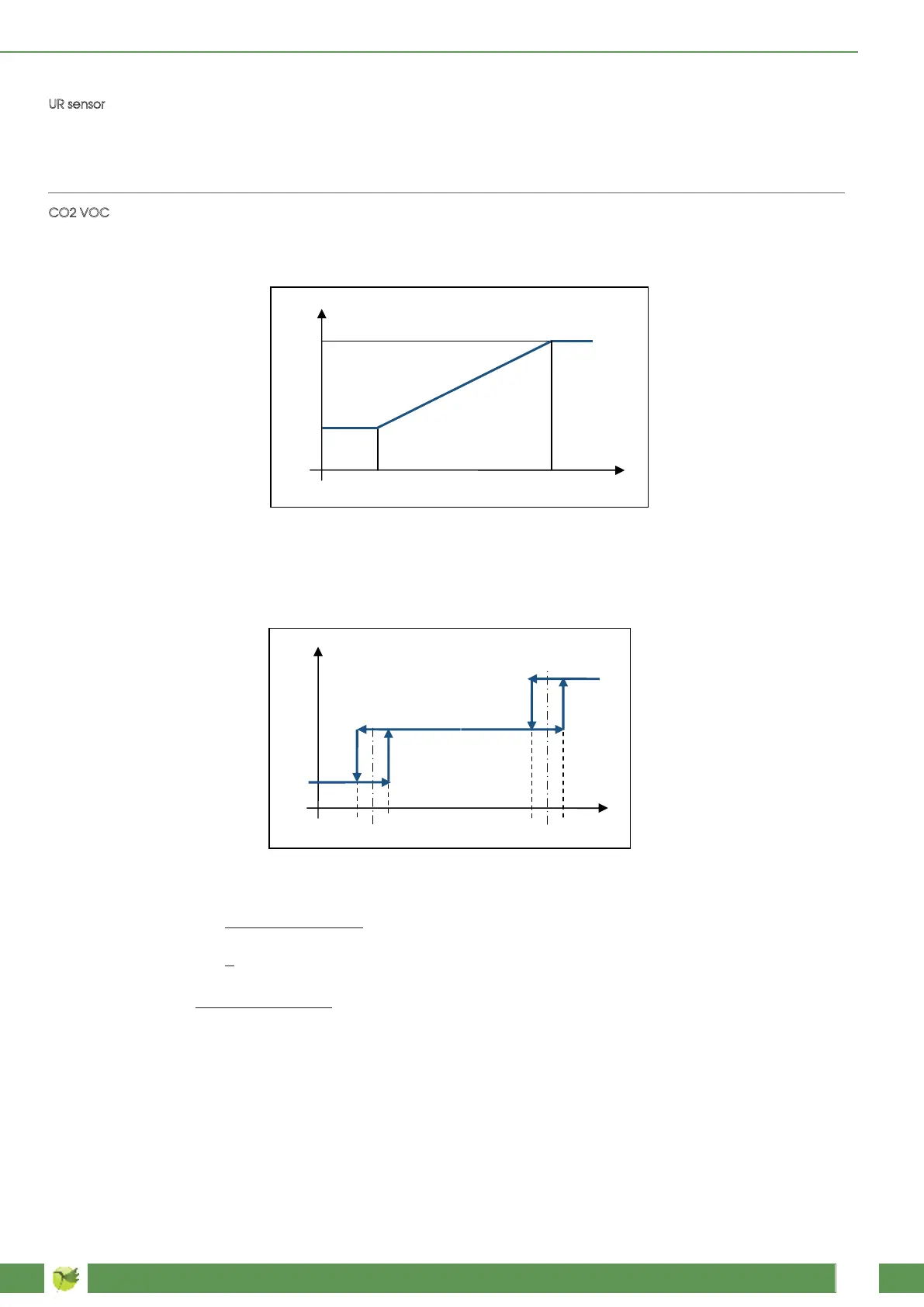
CO2 VOC
The fan speed will be controlled by a relative humidity (RH) sensor with 0-10V output and will have a linear trend
between 0 and 100% RH (0V corresponds to 0% RH and 10V corresponds to 100% RH); if the external signal of the
RH sensor takes the 0V value, the control will display a problem with the sensor. See graphs of the segnale es
parameter. In this case, AutoMin% corresponds to the relative humidity value for which the air quality is held to be
excellent , AutoMax% corresponds to the relative humidity value for which the air quality is held to be very bad.
The
fan speed will be controlled by a CO2 (or CO2-VOC) sensor with a 0-10V output and will have a linear trend
between 0 and 2000 ppm (0V corresponds to 0% ppm and 10V corresponds to 2000 ppm); if the external signal of
the CO2 sensor takes the 0V value, the control will display a problem with the sensor. For a unit equipped with
adjustable speed fans.
Where AutoMin ppm corresponds to the CO
2 (CO2-VOC) concentration for which the air quality is held to be
excellent, AutoMax ppm corresponds to the CO2 (CO2- VOC) concentration for which the air quality is held to be
very bad.
For a unit equipped with 3-speed fans.
FAN speed
SP.3
SP.2
SP.1
SP.1,2%
INPUT signal
-∆|+∆
SP.2,3%
-∆|+∆
SP.1,2% SP.2,3% and Δ values depend on the values of both parameters AutoMin ppm and AutoMax ppm accor-
ding to the following formulas:
Automax ppm - AutoMin ppm
SP. 1,2% = + AutoMin ppm
10
Automax ppm - AutoMin ppm
12
5
,3 x (AutoMax ppm - AutoMin ppm) + AutoMin ppmSP. 2,3% =SP.
7
2
∆ =