User’s Guide – Multi-GEM 12
For the more information of Multi-GEM 12, please refer full version manual (soft copy)
that you can get via e-mail and homepage.
Multi-GEM 12 is installed in electric distribution and local panels for supplying power
to their production line. It measure the voltage and current, and calculate the power in
real-time. You can monitor and manage the energy of equipment. It can help to
operate efficiently and to reduce the energy consumption.
This equipment is capable of accurate analysis and diagnosis equipment for various
problems of energy management and power plants.
Multi channel power meter (Multi-GEM 12) is able to measure and monitor multi
electric power loads.
Max 12 single phase or 4 3P4W feeders power monitoring
Measurement : V (L-N, L-L) , A, Hz, PF, Unbalance, Power(P,Q,S), Energy (P,Q,S).
1.0/0.5 Class accuracy for power measurement conformed by IEC61557-12
Flexible application for the single phase/ 3phase 4wire / 3phase 3wire power line.
Sag/Swell / Over Current / Temp Alarm.
Total Harmonics Distortion (THD)
Support Ethernet (Modbus TCP) and Wi-Fi.
Support Cloud energy platform.
Compact size for easy installation in narrow space (62 x 96 x 56 mm)
Measurement
1. Introduction
2. Characteristics
3. Specification
Model
Power system
Power Input
Communication
Usage
Altitude up to
Operating Temperature
Storage Temp.
Humidity
Standards
Voltage
Frequency
CT type
Measuring
Inputs
Rating
Specification
3P3W, 3P4W, 1P2W, 1P3W
100~240 VAC, Max. 50/60 Hz
50/60 Hz
100mA or 333mV
LAN
Wi-Fi (Option)
Indoor
2,000 m
Maximum relative humidity 80% R.H. for tempera-
tures up to 31 °C decreasing linearly to 50 % R.H.
relative humidity at 40 °C
IEC 61557-12
Phase voltage
Line voltage
Line current
Active power
Reactive power
Apparent power
Frequency
Unit
V
V
A
W
Var
VA
Hz
Digit
0.0 ~ 99,999
0.0 ~ 99,999
0.0 ~ 99,999
±0 ~ 999,999,999
±0 ~ 999,999,999
0.0 ~ 999,999,999
45.00 ~ 65.00
±0.2% Reading
±0.2% Reading
±0.2% Reading
Class 0.5S
Class 0.5S
Class 0.5S
Item Accuracy
Display
Power Factor
Temp. (NTC)
Voltage unbalance
Current unbalance
Phase angle
THD
Active Energy
Reactive Energy
Apparent Energy
Unit
%
%
%
°
%
kWh
kVarh
kVAh
± 100.00
-20.0 ~ 100.00
00 ~ 100.00
00 ~ 100.00
00 ~ 360.00
00 ~ 100.00
0.0 ~ 999,999,999
0.0 ~ 999,999,999
0.0 ~ 999,999,999
±0.5% Full scale
Item Accuracy
Display
It needs to avoid a place where direct interference exists like as high temperature and
electromagnetic field for the installation. Please check the environment condition
around Multi-GEM 12 below for a correct operation.
1. Create two 4mm holes using the mounting hole guide in manual.
2. Fix the product by using bolts provided.
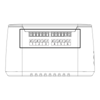
5. Name of parts
4. Installation
No.
1
2
3
4
5
6
7
8
Name
Screw fixing holes
Control Power
Voltage Input
Ethernet Port
CT Port
Status LED
Wall mount
Upgrade Port
Description
Screw holes for fixed terminals
Supply the control power to the gems 3512 (AC/DC 100~240V)
, Wire Size : 12 ~ 24AWG
N : Neutral (AC), -(DC) connection, A : Line (AC), +(DC) connection
Voltage input terminal for measurement , Wire Size : 12 ~ 24AWG
Communication with Master (Modbus Slave)
Protocol : Modbus TCP/IP
Speed : 10/100 Mbps Automatic selection
CT Input Terminal
Cloud Version
Bolt spec : D = 4mm / L = 55mm
Upgrade Port
Item
Location
Operation temp,
Storage temp,
Operation humidity
Condition
Indoor
-10°C to 55°C [14°F to 122°F]
-25°C to 70°C [-13°F to 158°F]
Non condensation,5% R.H. to 80% R.H.
Power connection
WiFi router connection ready (Soft AP)
WiFi router connection ready
The connection attempt to the Cloud
Device Authentication after the Cloud connect
Equipment installation complete
Firmware Update
ON
ON
OFF
BLK
OFF
GLOW
BLK
BLK
OFF
OFF
OFF
OFF
OFF
BLK
OFF
LED
LEFT CENTER RIGHT
Wall mount : 4mm hole, 2EA
46mm
68mm
CTs are connected to this terminal. The terminal must meet the correct side of CT to
measure power correctly.
Example of CT wiring
side is at S2( ) of CT
How to use
( )