POPULUS P – Access controller
POPULUS P – ACCESS CONTROLLER
The Populus P is an access controller that controls up to 8 readers
and 4 outputs for electric strikes. It is designed for residential and
business buildings, offices, shops, etc.
The entire set-up procedure is carried out with the software. The
controller allows access for up to 16000 users. It is intended for
controlling entries, exits and passes of users in the system and
controlling sliding doors, ramp, el. strike, turning alarm on/off… It
needs to be set with BLOCKER, V7 or CODEKS software.
It may also be used as a standalone controller. In this case, the
entire set-up procedure is carried out with master card or code.
User cards and codes can either be registered or deleted. The
controller allows access for up to 500 users (1 master card + 500
user cards or codes).
The SDK is also available for this controller. If a user or software
producer wants to develop its own application, please contact us.
TECHNICAL DATA
POPULUS P-1-3P and POPULUS P-1-3P-NET
1x direct or Wiegand, 1x protocol
1x door status, 1x button
POPULUS P-2-3P and POPULUS P-2-3P-NET
2x direct or Wiegand, 2x protocol
2x door status, 2x button
POPULUS P-4-3P and POPULUS P-4-3P-NET
4x direct or Wiegand, 4x protocol
4x door status, 4x button
*if Populus P is in Spider mode, the same data applies
(F100) T1AL, 250 V (5x20mm)
Real time clock, battery backup
(max. ten hours)
Operation at an altitude of
Class II - This is a class A
product. In a domestic
environment this product may
cause radio interference in which
case the user may be required to
take adequate measures.
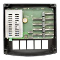
CONNECTOR DESCRIPTION
Connectors are marked on the circuit board with AC, LAN, SYS,
COM, RDR and DOOR.
CONNECTOR AC – Power supply
Power supply
110 – 230 V AC
50–60 Hz
CONNECTOR LAN – Ethernet connection
CONNECTOR SYS – backup battery connection
CONNECTOR COM – RS485 communication connection
CONNECTOR RDR1, RDR2, RDR3, RDR4 – reader connection
CONNECTOR DOOR1, DOOR2, DOOR3, DOOR4 – sensor,
button, el. strike and relay connections
Door status switch input
active=GND
Push button input
active=GND
El. strike output
active=GND
Power Supply
The controller can operate within a 110-230V AC, 50–60Hz input
range. The output power of the in-built power supply is 30W, 13.8V
fulltime. The power supply has protection against both short
circuits and current overload. In the event of protection activation,
the power will be switched off for 5s. If this is repeated 20 times,
the controller will switch off until electrical resetting takes place
(unplugging from mains voltage). This protection is activated if
external consumption exceeds 2A.
An appropriate disconnect device should be provided external to
the equipment. A multi-strand/stranded flexible wires connected to
the unit mains input require ferrules.