Do you have a question about the Japan Radio Co. jlr-21 and is the answer not in the manual?
Explanation of symbols used in the manual for safety and proper operation.
Critical warnings about equipment misuse, disassembly, electrical shock, and fire hazards.
Cautions regarding environmental conditions, installation, and component usage to prevent damage.
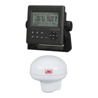
Description of the standard components included with the GPS compass system.
Overview of the equipment's primary functions in determining ship heading and position.
Highlights key features of the GPS compass, including accuracy, speed, and display.
Details the standard configuration of components for JLR-21 and JLR-31 models.
Provides dimensional drawings and mass specifications for the display and sensor units.
Illustrates the system connections between the display unit, sensor, and other equipment.
Guidelines and cautions for installing the GPS compass sensor unit.
Instructions for mounting the display unit in various configurations (desk, wall, ceiling).
Details on connecting the sensor, power, and external devices to the display unit.
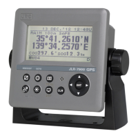
Identifies and describes the components and controls of the display unit.
Illustrates and names the components of the sensor unit.
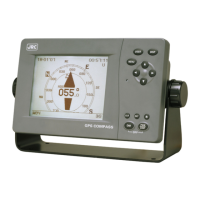
Introduces various display screens: Compass, Bow Heading, Navigation, and Turn Rate.
Describes the graphical displays and information shown on the Compass screens (A-F).
Explains the numerical display of Bow Heading, SOG, and COG.
Details the display of latitude, longitude, and RAIM information.
Describes the display of ship's rate of turn.
Shows display of ship speeds and bearing, including tidal current data.
Explains the trend graph display for roll/pitch, heaving, and SOG.
Describes how to calculate distance and bearing between two points.
Shows the screen for accessing the Configuration menu.
Provides a comprehensive list of all menu options and their settings.
Covers fundamental operations like turning the unit on/off and adjusting display settings.
Details settings for Display, Heading, GPS, SBAS, Beacon, System, Data I/O, Version, Others, and Language.
Outlines functions for Antenna Check, Input Check, Self-Diagnosis, Demo, Product Type, Reset, Software Update, and CCRP.
Provides guidelines for routine cleaning and parts securing.
Lists possible alarms, their message numbers, contents, and causes.
Offers guidance on identifying and resolving common problems with the equipment.
Information regarding the standard warranty period and policies.
Details on the availability of functional repair parts.
Instructions on what information to provide when requesting service or repairs.
Advice on periodic checks and inspections to maintain equipment performance.
Guidance on observing local regulations for equipment disposal.
Safety precautions and instructions for disposing of the lithium battery.
Technical specifications for the display unit, including panel, power, environment, and dimensions.
Technical specifications for the sensor unit, including electrical, environmental, and dimensional data.
| Channels | 12 |
|---|---|
| Tracking Sensitivity | -160 dBm |
| Receiver Type | L1 C/A code |
| Frequency | 1575.42 MHz |
| Velocity Accuracy | 0.1 m/sec (50%) |
| Data Output | NMEA 0183 |
| Weight | 500 g |