ENGLISH OPERATION MANUAL
JB SYSTEMS® 3/24 LM140
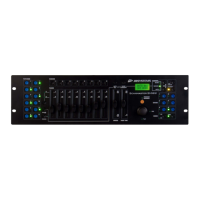
FUNCTIONS (FRONT)
Important to know is that you can use this device in 2 ways:
As a Light Modulator: ALL DIP-switches must be in OFF position. Then you can use this unit
to control lamps and projectors.
As a Switch Pack: you set the DIP-switches (see number 8 for more information ). You can use
a DMX-controller to switch projectors/small light effects ON/OFF. When you use this device as
a Switch Pack, controls 2 to 7 are disabled.
1. Power Switch: used to turn the unit ON/OFF.
2. Flash Buttons: Press the flash buttons to set the output of the corresponding channels to maximum.
The LEDs display the state of the channels.
3. Audio/Chase Button: You can switch between the 2 modes:
Red LED is lit: the Audio Chase mode is activated. The built-in chase programs are activated by
sound.
Green LED is lit: the Static Chase mode is activated. The speed of the built-in chase programs
is controlled by the speed knob ( see number 4 for more information ).
4. Speed Knob: Used to adjust the speed of the channels when you use the unit in Static Chase mode.
5. Program Knob: Used to choose one of the built-in programs.
ENGLISH OPERATION MANUAL
JB SYSTEMS® 4/24 LM140
6. Sensitivity Knob: Used to adjust the sensitivity of the built-in microphone when you are working in
Audio Chase mode.
7. Stand By Button: Used to blackout the unit
8. DMX Adresses: To set the DIP-Switches, refer to the dmx values below to set the correct address.
On the front of the LM140 you will see that each of the first 9 DIP-switches corresponds to a certain
DMX-value (DIP-switch 10 is not used):
You can combine the values of these switches to obtain any starting address between 1 and 512:
Begin address = 01 switch 1=ON values: 1
Begin address = 05 switch 1+3=ON values: 1+4 = 5
Begin address = 09 switch 1+4=ON values: 1+8 = 9
Begin address = 13 switch 1+3+4=ON values: 1+4+8 = 13
…
Begin address = 62 switch 2+3+4+5+6=ON values: 2+4+8+16+32 = 62
Important: When you use the unit as a switch pack, the light effect/projector will be switched off in the
range from 0-111 ( the corresponding Channel LED is NOT lit ). The light effect will be switch on in the
range from 111-255 ( the corresponding Channel LED is lit ).
FUNCTIONS (REAR)
1. DMX-input Connector
2. DMX-output Connector
3. Fuse holder Mains input
4. Channel Output fuses
5. Channel Outputs: These outputs are equipped with IEC sockets.
6. Mains Cable
SPECIFICATIONS
Power Input: AC 230 V ~ 50 Hz
Channel Output fuses: 6.3 A /250V (5 x 20 mm)
Maximum power per channel: 1200W
Total Maximum power: 3600 W
Mains Fuse: 1 A / 250 V (5 x 20 mm)
DMX input/output: 3pin XLR
Audio input: None, internal microphone
Size: 482 x 160 x 44 mm
Weight: 1,8 kg
Every information is subject to change without prior notice
You can download the latest version of this user manual on our website: www.beglec.com
Dip #1 #2 #3 #4 #5 #6 #7 #8 #9
Value 1 2 4 8 16 32 64 128 256