Do you have a question about the jbc JT and is the answer not in the manual?
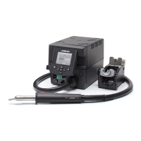
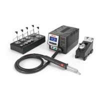
Lists the JTU Hot Air Control Unit as part of the packing list.
Lists the JTS Stand as part of the packing list.
Lists the JTT Heater Hose Set as part of the packing list.
Lists the Power Cable as part of the packing list.
Explains the Thermocouple Type K connection for activating the suction pump.
Details the Suction Tube and its purpose for tripods and extractors.
Identifies Extractor 64 (20x26mm) by reference number.
Identifies the JTS Stand by reference number.
Identifies various connectors: USB-A, Heating Element, Hot Air Button, Auxiliar, Equipotential, USB, RS232, Power Socket, Fuse.
Describes the Status Bar showing time, temperature, and flow indicators.
Details the indicator for instant power supplied to the heater.
Shows current and selected air/TC temperatures.
Shows the selected target air flow rate.
Provides access to general station information.
Details the available menu options: Station, Tools, Counters, Language, Reset.
Enables setting or editing up to 25 air flow and temperature profiles.
Allows detailed editing of temperature and air flow profiles with data points.
Lists options for profile management: add, delete, load, save, exit.
Shows real-time power, temperature, and external temperature figures in graph format.
Instructions on adjusting the tool holder angle to suit work position.
Press the start/stop button to blow hot air; stops when pressed again.
Press the Pedal (not included) to blow hot air; release to stop.
Tool stops blowing when returned to the stand for safety.
Position the extractor with the appropriate suction cup and press the suction button.
Heat the component using the hot air station.
The component lifts off automatically when the solder melts.
Recommends using the protector + tripod for small components.
Recommends using the manual extractors for large components.
Details the Pick & Place tool by reference number T260-A.
Lists Bent and Straight Needles Sets for SMDs.
Details the Suction Cup Set accessory for various components.
Instructions on selecting needle/cup and using suction for pick and place.
Lists various protector accessories with dimensions and references.
Lists various extractor accessories with dimensions and references.
Lists tripod accessories with dimensions and references.
Details manual extractor accessories with dimensions.
Station regulates air temp to maintain external TC temp.
Station cuts air supply when external TC temp is reached.
Instructions on fixing TC with Kapton Tape for ESD safety.
Turn the tool off and handle with care; heating element and nozzle are hot.
Lists compatible nozzles for JTT with JTU stations, including shapes and sizes.
Procedure for adjusting loosely fitting nozzles for secure attachment.
Identifies the handle for JTT and the heating element for JTT.
Step-by-step guide to unplugging, unscrewing, fitting, and tightening the hose set.
Guidelines for cleaning station screen/casing and inspecting cables/tubes.
Procedure for safely replacing a blown fuse in the station.
Guidance on using original JBC parts and authorized repair services.
Prohibits misuse, working on live parts, leaving unattended, covering vents; advises on flux/fumes.
Emphasizes clean workspace, protective gear, handling tin waste, and safe use by children.
Specifies JTSE-1A/2A models, input fuse, rated current, and nominal power.
Details temperature selection, cool mode, ambient temp, air flow, and vacuum.
Provides dimensions, weight, connectors, and ESD protection status.
Confirms compliance with CE standards.
Details the 2-year warranty against manufacturing defects.
Excludes wear/misuse; provides info for extended warranty registration.
Instructions for proper electronic equipment disposal according to EU directive.
| Brand | jbc |
|---|---|
| Model | JT |
| Category | Power Tool |
| Language | English |