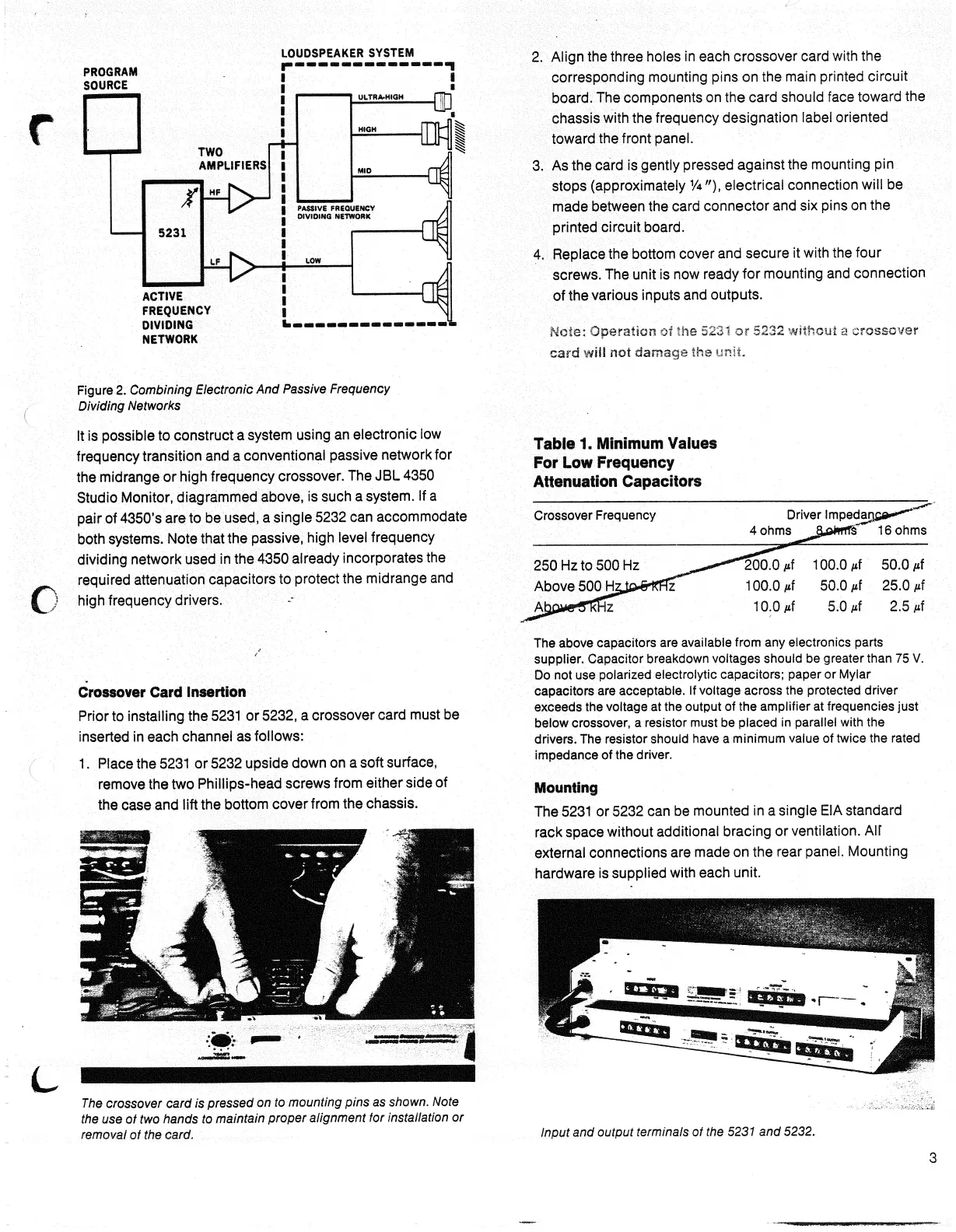
LOUDSPEAKER SYSTEM
PROGRAM
SOURCE
ACTIVE
FREQUENCY
DIVIDING
NETWORK
2.
Align the three holes
in
each crossover card with
the
corresponding mounting pins
on the
main printed circuit
board.
The components
on the
card should face toward
the
chassis with the frequency designation label oriented
toward the front panel.
3.
As
the card
is
gently pressed against the mounting
pin
stops (approximately
1
/4"), electrical connection will
be
made between
the
card connector and
six
pins
on the
printed circuit board.
4.
Replace the bottom cover and secure
it
with
the
four
screws. The unit
is now
ready
for
mounting and connection
of the various inputs and outputs.
Mote:
Operation
01
the 5231
or
5232 without a crossover
card
will not damage the unit-
It
is
possible
to
construct
a
system using
an
electronic
low
frequency transition and
a
conventional passive network for
the midrange
or
high frequency crossover. The JBL 4350
Studio Monitor, diagrammed above,
is
such
a
system.
If a
pair
of
4350's are
to be
used,
a
single 5232 can accommodate
both systems. Note that the passive, high level frequency
dividing network used
in
the 4350 already incorporates
the
required attenuation capacitors
to
protect the midrange
and
high frequency drivers.
Crossover Card Insertion
Prior to installing the 5231
or
5232,
a
crossover card must
be
inserted
in
each channel
as
follows:
1.
Place the 5231
or
5232 upside down
on a
soft surface,
remove the two Phillips-head screws from either side
of
the case and lift the bottom cover from the chassis.
4
Table 1.
Minimum
Values
For
Low Frequency
Attenuation Capacitors
The
above capacitors
are
available from
any
electronics parts
supplier.
Capacitor breakdown voltages should
be
greater than
75 V.
Do
not use
polarized electrolytic capacitors; paper
or
Mylar
capacitors
are
acceptable.
If
voltage across
the
protected driver
exceeds
the
voltage
at the
output
of the
amplifier
at
frequencies just
below
crossover,
a
resistor must
be
placed
in
parallel with
the
drivers.
The
resistor should have
a
minimum value
of
twice
the
rated
impedance
of the
driver.
The
crossover
card
is
pressed
on to
mounting
pins
as
shown.
Note
the
use of two
hands
to
maintain
proper
alignment
tor
installation
or
removal
of the
card.
Input
and
output terminals
of the 5231 and
5232.
TWO
AMPLIFIERS
HF
LF
5231
LOW
PASSIVE
FREQUENCY
DIVIDING
NETWORK
ULTRA-HIGH
HIGH
MID
Figure
2.
Combining
Electronic
And
Passive
Frequency
Dividing
Networks
Crossover
Frequency
Driver
Impedaqe®^^
4
ohms
cl£>mf$ 16
ohms
250
Hz to
500
Hz _^*»
Above
500JHgJf>^r1z
. '20O0
/if
100.0
/xf
50.0
/if
100.0
/if
50.0
/if
25.0
/if
10.0/if
5.0/if 2.5 /if
Mounting
The 5231
or
5232 can
be
mounted
in a
single EIA standard
rack space without additional bracing
or
ventilation.
Air
external connections
are
made
on the
rear panel. Mounting
hardware
is
supplied with each unit.
 Loading...