Connections
Shielded cable
is
required
at
all input and output signal
con-
nections.
If
cable lengths greater than 15
to
20 feet are
required between the electronic crossover and the power
amplifier,
it is
recommended that isolation transformers
or
isolation line amplifiers be connected
to
the output
of
the
crossover to reduce the possibility
of
induced RF interference
or hum.
Input Connections—Inputs
to
the 5231 and 5232 are for an
unbalanced line level source. Screw terminals on the rear
panel are provided for connection
of
each input and are
clearly identified.
Output Connections—Each output channel can deliver 6.2
volts into 2000 ohms (+18 dB referenced
to
0.775 volts).
A
separate pair
of
screw terminals, located on the rear panel,
is
provided for the low and high frequency output
of
each
channel.
Outputs will drive the high-impedance (bridging) line
input
of
any conventional amplifier. Typically, the impedance
of
a
bridging input
is at
least 5000 ohms (usually 10,000 ohms
or more), therefore, two
or
more power amplifiers can
be
driven by
a
single electronic frequency dividing network.
PROGRAM
SOURCE
AMPLIFIER
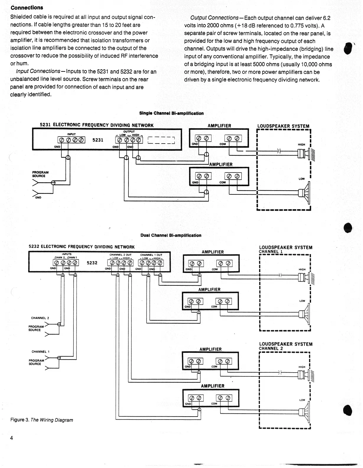
Dual Channel Bi-ampiificatlon
5232 ELECTRONIC FREQUENCY DJVIDING NETWORK
PROGRAM
SOURCE
PROGRAM
SOURCE
5232
Figure 3.
The
Wiring
Diagram
AMPLIFIER
AMPLIFIER
AMPLIFIER
AMPLIFIER
4
Single Channel
Bi-amplification
S231 ELECTRONIC FREQUENCY DIVIDING NETWORK
AMPLIFIER
LOUDSPEAKER SYSTEM
HIGH
LOW
5231
CHANNEL
2
CHANNEL
1
LOUDSPEAKER SYSTEM
CHANNEL
1
LOUDSPEAKER SYSTEM
CHANNEL
2
HIGH
LOW
HIGH
LOW
 Loading...