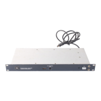
Figure 5. Blank Crossover Card
Table 2.
Blank Crossover Card
Component Values
Resistors are all %-Watt, 5% tolerance. Capacitors are all
5%
tolerance, metalized polyester.
Crossover
Frequency
(Hertz)
Capacitors
C1'-C5'
(microfarads)
Resistors
R1'-R5'
(kilohms)
900
.012 10
1100
.010
10
1200
.0082
11
1500
.0082 9.1
2000
.0047
12
2500
.0018
24
5000
.0015
15
6000
.0012
16
7000
.0015
11
9500
.0012
10
1.
Crossover characteristics of the 51-5140 are tailored specifically for the
4340 Studio Monitor.
2.
m'and
R2'only. The value for R3,' R4'and R5' is 22 kilohms, part
number 10944.
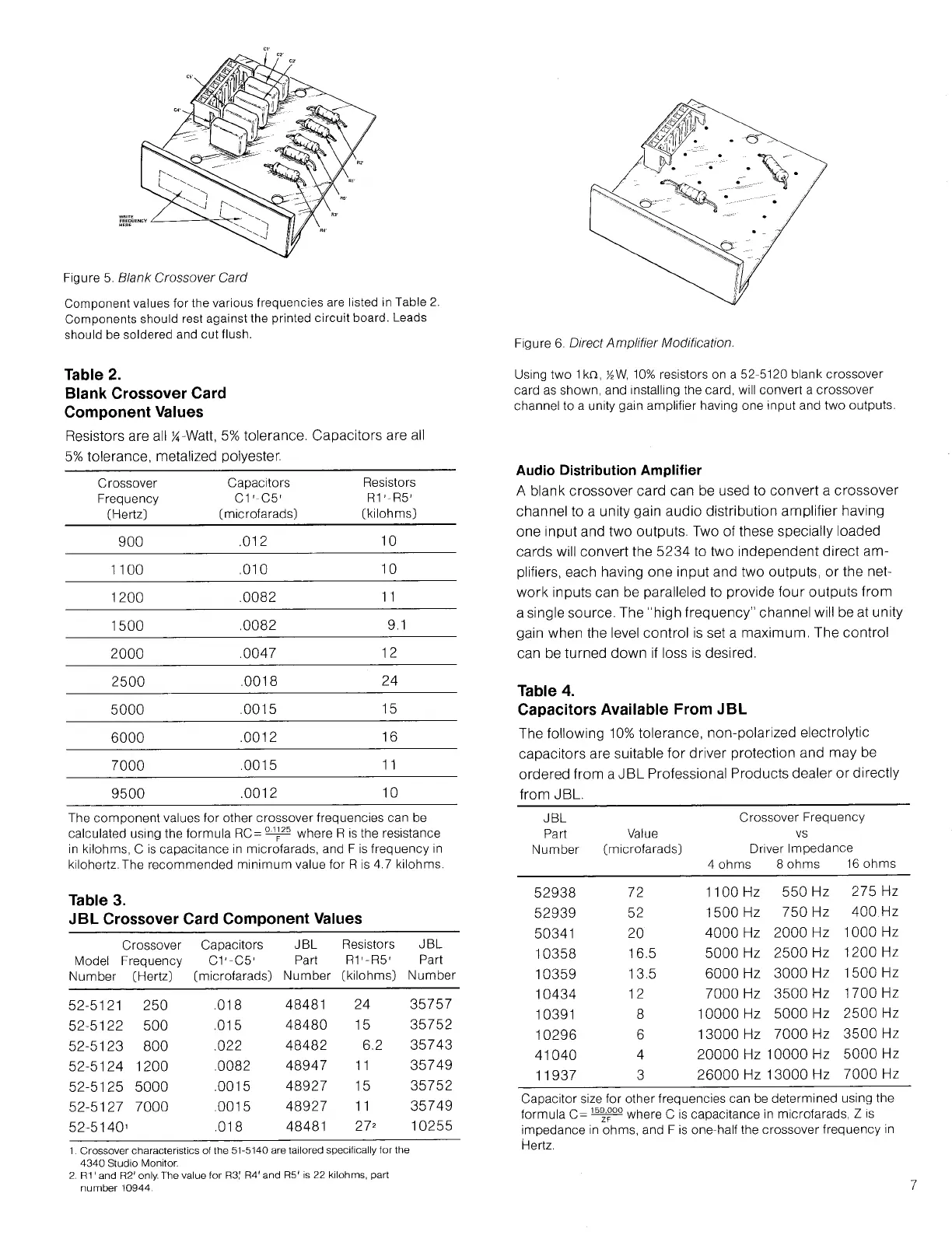
Using two
1
kn, y
2
W, 10% resistors on a 52-5120 blank crossover
card as shown, and installing the card, will convert a crossover
channel to a unity gain amplifier having one input and two outputs.
Audio Distribution Amplifier
A blank crossover card can be used to convert a crossover
channel to a unity gain audio distribution amplifier having
one input and two outputs. Two of these specially loaded
cards will convert the 5234 to two independent direct am-
plifiers, each having one input and two outputs, or the net-
work inputs can be paralleled to provide four outputs from
a single source. The "high frequency" channel will be at unity
gain when the level control is set a maximum. The control
can be turned down if loss is desired.
Table 4.
Capacitors Available From JBL
The following
10%
tolerance, non-polarized electrolytic
capacitors are suitable for driver protection and may be
ordered from a
JBL
Professional Products dealer or directly
from
JBL.
JBL
Crossover Frequency
Part
Value
vs
Number
(microfarads)
Driver Impedance
4 ohms
8 ohms
16 ohms
52938
72
1100 Hz 550 Hz
275 Hz
52939
52
1500 Hz
750 Hz
400 Hz
50341 20
4000 Hz
2000 Hz
1000 Hz
10358
16.5 5000 Hz
2500 Hz
1200 Hz
10359
13.5
6000 Hz
3000 Hz
1500 Hz
10434
12
7000 Hz 3500 Hz
1700 Hz
10391
8 10000 Hz
5000 Hz
2500 Hz
10296
6
13000 Hz 7000 Hz
3500 Hz
41040
4
20000 Hz 10000 Hz
5000 Hz
11937
3
26000 Hz 13000 Hz
7000 Hz
Capacitor size for other frequencies can be determined using the
formula C=
]b3
z
°
00
where C is capacitance in microfarads, Z is
impedance in ohms, and F is one-half the crossover frequency in
Hertz.
Figure 6. Direct Amplifier Modification.
Component values for the various frequencies are listed in Table 2.
Components should rest against the printed circuit board. Leads
should be soldered and cut flush.
The component values for other crossover frequencies can be
calculated using the formula RC= where R is the resistance
in kilohms, C is capacitance in microfarads, and F is frequency in
kilohertz.The recommended minimum value for R is 4.7 kilohms.
Table 3.
JBL Crossover Card Component Values
Crossover
Capacitors
JBL Resistors
JBL
Model Frequency C1'-C5'
Part
R1'-R5'
Part
Number
(Hertz) (microfarads)
Number (kilohms)
Number
52-5121 250
.018
48481
24
35757
52-5122 500
.015
48480 15
35752
52-5123 800
.022
48482 6.2 35743
52-5124 1200
.0082
48947 11
35749
52-5125
5000
.0015
48927 15
35752
52-5127 7000 .0015
48927 11
35749
52-5140'
.018
48481
27*
10255
 Loading...