EasyManua.ls Logo

JBL 5233 - User Manual

JBL 5233
12 pages
Print Icon
To Next Page IconTo Next Page
Loading...
Professional Series
Installation and
Service Manual
Electronic Frequency
Dividing Networks
5233 Single Channel
5234 Dual Channel

Other manuals for JBL 5233

Question and Answer IconNeed help?

Do you have a question about the JBL 5233 and is the answer not in the manual?

Summary

Owners Instructions and Specifications

Specifications Overview

Detailed technical specifications for the dividing networks, including gain, output, distortion, and frequency response.

System Setup Guidance

Procedures for connecting the network and configuring it for bi-amplification or tri-amplification.

Installation and Wiring Diagrams

Network Installation Procedure

Steps for installing the electronic frequency dividing network within a sound system.

System Wiring Configurations

Visual guides for bi-amplification and tri-amplification system configurations.

Operation and Adjustment Procedures

Wiring Verification and Transducer Phasing

Crucial checks for correct connections, transducer phasing, and preventing damage.

Level Control Calibration

Procedures for balancing driver levels for optimal sound system performance.

Service, Components, and Protection

Service and Voltage Conversion

Instructions for installing crossover cards and converting operating voltage.

Custom Crossover Network Assembly

Information on building custom crossover networks using blank cards.

Driver Protection Guidelines

Recommendations for protecting drivers from switching transients.

Overview

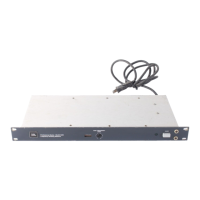
The JBL Professional Series 5233 Single Channel and 5234 Dual Channel Electronic Frequency Dividing Networks are designed for use with studio monitor or sound reinforcement loudspeaker systems where bi-amplification or tri-amplification is desired. These devices serve to separate an audio signal into high and low frequency bands, which are then fed to appropriate power amplifiers for driving loudspeaker system components.

Function Description:

The 5233 (single channel) and 5234 (dual channel) units feature differential high impedance inputs, unity gain in the passband, and unbalanced low impedance outputs. The 5233 provides a single channel crossover, while the 5234 offers two separate channels with independent crossover action, making it suitable for stereo installations. The crossover frequency for each channel is determined by plug-in modules, which are available for various commonly used frequencies. Filter slopes can be either 12 dB or 18 dB per octave, with high and low frequency outputs attenuated by 3 dB at the crossover point. Special crossover cards are also available for specific JBL bi-amplified studio monitors like the 4343 and 4350. Blank cards can be used to construct custom crossover networks for other frequencies.

The network receives program signals from a line-level source (e.g., preamplifier, studio console, or portable mixer) and divides them into high and low frequency bands. These outputs then drive the respective power amplifiers and loudspeaker components. Input connections can be balanced or unbalanced, while output connections are unbalanced, requiring shielded cable. For longer output cable lengths (greater than 4.5 to 6 meters), isolation transformers are recommended to reduce radio frequency interference or hum. The outputs can deliver +18 dB (6.2 V into 600 Ω) and can drive the line inputs of conventional amplifiers, with two or more power amplifiers being driven from each output.

The 5234 dual channel network can also be configured for tri-amplification by connecting the low frequency output of Channel 2 to the input of Channel 1. This allows Channel 1 outputs to drive midrange and low frequency amplifiers. When a midrange or high frequency driver is directly connected to a power amplifier, a series capacitor is recommended to attenuate unwanted low frequency "on-off" switching transient signals that could damage the driver. Passive, high-level frequency dividing networks in JBL studio monitors designed for bi-amplification already include these protective attenuation capacitors.

Important Technical Specifications:

  • Gain: 0 dB in the passband.
  • Rated Output: 6.2 V (+18 dB ref. 0.775V).
  • Distortion (THD): Less than 0.5% (20-20,000 Hz at rated output), less than 0.2% (20-20,000 Hz at +10 dB ref. 0.775 V).
  • Frequency Response: ±0.5 dB, 20-20,000 Hz.
  • Crossover Frequency: Selectable by plug-in module, 3 dB crossover point ±10%.
  • Filter Slope: 12 dB or 18 dB per octave.
  • Input Impedance: Greater than 50 kΩ.
  • Load Impedance: 600 Ω or greater.
  • Output Impedance: 47 Ω.
  • Channel Isolation: Greater than 60 dB, 20-20,000 Hz.
  • Signal/Noise Ratio: Greater than 90 dB, 20-20,000 Hz equivalent bandwidth.
  • Power Requirement: 5 W 120/240 V AC, 50/60 Hz.
  • Operating Temperature: Up to 55°C (132°F).
  • Dimensions: 44 mm x 483 mm x 194 mm deep (1¾ x 19 x 7⅝ in deep).
  • Mounting: 1 EIA standard rack space.
  • Net Weight: 1.8 kg (4 lb) either unit with accessory crossover card(s) installed.
  • Shipping Weight: 3.0 kg (6.5 lb) either unit.

Usage Features:

  • Front Panel Controls: Power switch, pilot light, and a high frequency level control for each channel are easily accessible on the front panel. The crossover frequency is indicated through a front panel window.
  • Rear Panel: A voltage change switch is located on the rear panel.
  • Rack Mounting: Both models can be mounted in one EIA standard rack space without additional bracing or ventilation. Mounting hardware is supplied.
  • Input/Output Connections: Screw terminals on the rear panel are provided for input and output connections. Balanced connections are shown in color, with a warning that exchanging HI and LO conductors will result in phase reversal.
  • Crossover Card Flexibility: Users can select from a range of pre-made crossover cards or assemble custom networks on blank cards. Component values for 12 dB/octave and 18 dB/octave blank crossover cards are provided, allowing for customization of crossover frequencies.
  • Driver Protection: Recommendations for series capacitors to protect midrange and high frequency drivers from low frequency transient signals are provided, along with tables for maximum capacitor values based on driver impedance and crossover frequency.
  • System Wiring Verification: A detailed procedure is outlined to verify correct wiring, emphasizing the importance of proper connections to prevent damage to loudspeaker components.
  • Transducer Phasing: Both objective (using a real-time third octave analyzer, condenser microphone, and pink noise) and subjective methods are described for establishing proper phase relationships between transducers for optimal sound character.
  • Level Control Adjustment: Instructions are provided for balancing levels of individual drivers in bi-amplified and tri-amplified systems, either objectively (using a real-time analyzer) or subjectively (using familiar program material or pink noise).

Maintenance Features:

  • Voltage Conversion: The units can operate from either 100-120 V AC or 200-240 V AC, 50/60 Hz sources. A SUPPLY VOLTAGE SELECT switch (S301) allows conversion between voltage ranges. Instructions include disconnecting power, sliding the switch, and changing the line cord/attachment plug. A warning is given against operating the unit with an incorrect voltage select switch setting.
  • Crossover Card Installation/Removal: Detailed steps are provided for installing a new crossover card, including removing the bottom cover, gently lifting the old card, aligning the new card with mounting pins, and securing it. The manual notes that operating the unit without a crossover card will not damage it.
  • Blank Crossover Card Assembly: Instructions for assembling custom crossover circuits on blank cards are provided, including component values and a formula for calculating values for other frequencies.
  • Component Information: Tables list component values (capacitors and resistors) for various crossover frequencies for both 12 dB/octave and 18 dB/octave cards.
  • Capacitor Availability: A list of suitable non-polarized electrolytic capacitors available from JBL for driver protection is provided.

JBL 5233 Specifications

General IconGeneral
BrandJBL
Model5233
CategoryNetwork Accessory
LanguageEnglish

Related product manuals