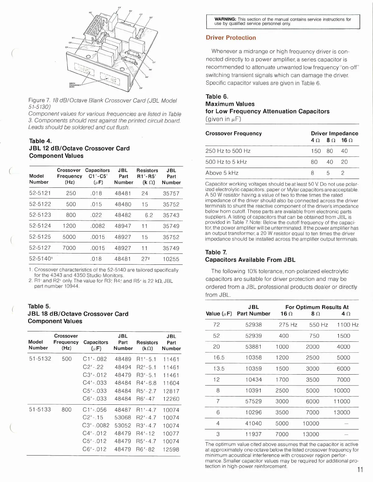
Figure 7. 18
dB/Octave
Blank
Crossover
Card
[JBL
Model
51-5130]
Component
values
for
various
frequencies
are
listed
in
Table
3.
Components
should
rest
against the printed circuit board.
Leads
should
be
soldered
and cut
flush.
Table 4.
JBL 12 dB/Octave Crossover Card
Component Values
Model
Number
Crossover
Frequency
(Hz)
Capacitors
C1-C5'
CmF)
JBL
Part
Number
Resistors
R1-R5'
fk n)
JBL
Part
Number
52-5121
250 .018 48481 24
35757
52-5122
500 .015
48480 15
35752
52-5123
800
.022
48482
6.2
35743
52-5124
1200 .0082
48947 11
35749
52-5125
5000 .0015
48927 15 35752
52-5127
7000
.0015 48927
1 1 35749
52-51 40
1
.018 48481
272
10255
1.
Crossover characteristics of the 52-5140 are tailored specifically
for the 4343 and 4350 Studio Monitors.
2.
R1' and R2' only. The value for R3; R4; and R5' is 22 kn, JBL
part number 10944.
Table 5.
JBL 18 dB/Octave Crossover Card
Component Values
Crossover
JBL
JBL
Model
Frequency
Capacitors Part
Resistors Part
Number
(Hz)
(MF)
Number
(kn)
Number
51-5132
500 C1
-.082
48489 R1
-5.1 11461
C2
-.22 48494
R2
-5.1 11461
C3 -.012 48479
R3
-5.1 11461
C4 -.033
48484 R4
-6.8 11604
C5 -.033 48484
R5
-2.7
12817
C6 -.033 48484
R6
-47
12260
51-5133
800 C1
-.056 48487
R1 -4.7
10074
C2
-.15 53068
R2 -4.7 10074
C3 -.0082
53052
R3 -4.7 10074
C4 -.012
48479
R4'
-12 10077
C5
-.012
48479
R5'
-4.7
10074
C6 -.012 48479
R6 -82
12598
1
ii or Pi i oti n
Whenever a midrange or high frequency driver is
con-
nected directly to a power amplifier, a series capacitor is
recommended to attenuate unwanted low frequency
"on-off"
switching transient signals which can damage the driver.
Specific capacitor values are given in Table 6.
Table 6.
Maximum Values
for Low Frequency Attenuation Capacitors
(given in ^F]
Crossover Frequency
Driver Impedance
4n 8n 16 n
250 Hz to 500 Hz
150 80 40
500 Hz to 5 kHz
80 40 20
Above 5 kHz 8 5 2
Table 7.
Capacitors Available From JBL
The following 10% tolerance, non-polarized electrolytic
capacitors are suitable for driver protection and may be
ordered from a JBL professional products dealer or directly
from JBL.
JBL
For Optimum Results At
Value 0(F) Part Number
16 n
8 n
4 n
72 52938
275 Hz 550 Hz 1100 Hz
52
52939
400 750 1500
20 53881
1000 2000 4000
16.5 10358
1200 2500 5000
13.5
10359 1500 3000 6000
12 10434
1
700
3500
7000
8 10391
2500 5000 10000
7 57529
3000 6000 11000
6 10296
3500 7000
13000
4
41040 5000 10000
-
3 11937
7000 13000
-
The optimum value cited above assumes that the capacitor is active
at approximately one octave below the listed crossover frequency for
minimum acoustical interference with crossover region perfor-
mance. Smaller capacitor values may be required for additional pro-
tection in high-power reinforcement.
WARNING: This section of the manual contains service instructions for
use by qualified service personnel only.
Capacitor working voltages should be at least 50 V. Do not use polar-
ized electrolytic capacitors; paper or Mylar capacitors are acceptable.
A 50 W resistor having a value of two to three times the rated
impedance of the driver should also be connected across the driver
terminals to shunt the reactive component of the driver's impedance
below horn
cutoff.
These parts are available from' electronic parts
suppliers. A listing of capacitors that can be obtained from JBL is
provided in Table 7. Note: Below the cutoff frequency of the capaci-
tor, the power amplifier will be unterminated. If the power amplifier has
an output transformer, a 20 W resistor equal to ten times the driver
impedance should be installed across the amplifier output terminals.
 Loading...