Service Instructions
The dividing networks are shipped with a 52-5120 cross-
over card with two 1000 ohm resistors installed in each
channel,
as in Figure 5. This card converts each channel into
a one-input, two-output unity gain distribution amplifier. Two
of these specially loaded cards will convert the 5234 to two
independent direct amplifiers, each having one input and two
outputs, or the network inputs can be paralleled to provide
four outputs from a single source. The "high frequency"
channel will be at unity gain when the level control is set at
maximum.The control can be turned down if loss is desired.
The 52-5120 crossover card must be removed before
installing the frequency selection card needed for the partic-
ular application. To install a new crossover card
1.
Place the 5233 or 5234 upside down on a soft surface,
remove the two Phillips-head screws from either side of the
case,
and lift the bottom cover from the chassis.
2.
Remove the old crossover card by lifting gently.
3. Align the three holes in each new crossover card with the
corresponding mounting pins on the main printed circuit
board.
The components on the card should face toward
the chassis with the frequency designation label toward
the front panel.
4.
As the card is gently pressed against the mounting pin
stops (roughly 6 mm,
%
in), electrical connection will be
made between the card connector and six pins on the
printed circuit board.
5. Replace the bottom cover and secure it with the four
screws. The unit is now ready for mounting and connection
of the various inputs and outputs.
NOTE:
Operation of the 5233 or 5234 without a crossover
card will not damage the unit.
WARNING:
This section of the manual contains service instructions for
use by qualified service personnel only.
Voltage Conversion
The 5233 and 5234 can be operated from either a 100-120
V AC or 200-240 V AC, 50/60 Hz source. The SUPPLY
VOLTAGE SELECT switch, S301, converts the unit from one
operating voltage range to the other. Use the following pro-
cedures to convert the preamplifier to a different voltage range.
1.
Disconnect the unit from the power source.
2.
Slide the SUPPLY VOLTAGE SELECT switch to the appro-
priate line voltage range.
3. Change the line cord and attachment plug to match the
power source receptacle or use a 120-to-240 V adapter
(not provided). The attachment plug and/or line cord
used for 240 V AC mode in the U.S. and Canada
is U.L. listed and OS.A.Certified. For use in othercountries
line cord selection should be based on local regulations
governing 240 V AC 50/60 Hz supply source.
Table 1.
Voltage Wiring Code
Switch S301 Switch S201
Ground,
Terminal 1
Terminal 1
E401
U.S.A.
Black White
Green
Europe
Blue
Brown
Green/Yellow
CAUTION:
This unit may be damaged if operated with the supply
voltage select switch set incorrectly for the line voltage applied.
Blank Crossover Card Assembly
In addition to the standard crossover cards, circuits for
other crossover frequencies may be assembled on blank
crossover cards using standard components. Filter slopes
(12 or 18 dB per octave) are identical to those of the stan-
dard crossover cards. The crossover frequency can be written
on the card bracket and will appear through the front panel
window of the network.
The
crossover
card
is
pressed
on to mounting
pins
as
shown
Note the use of two
hands
to
maintain
proper
alignment for
installation or removal of the card.
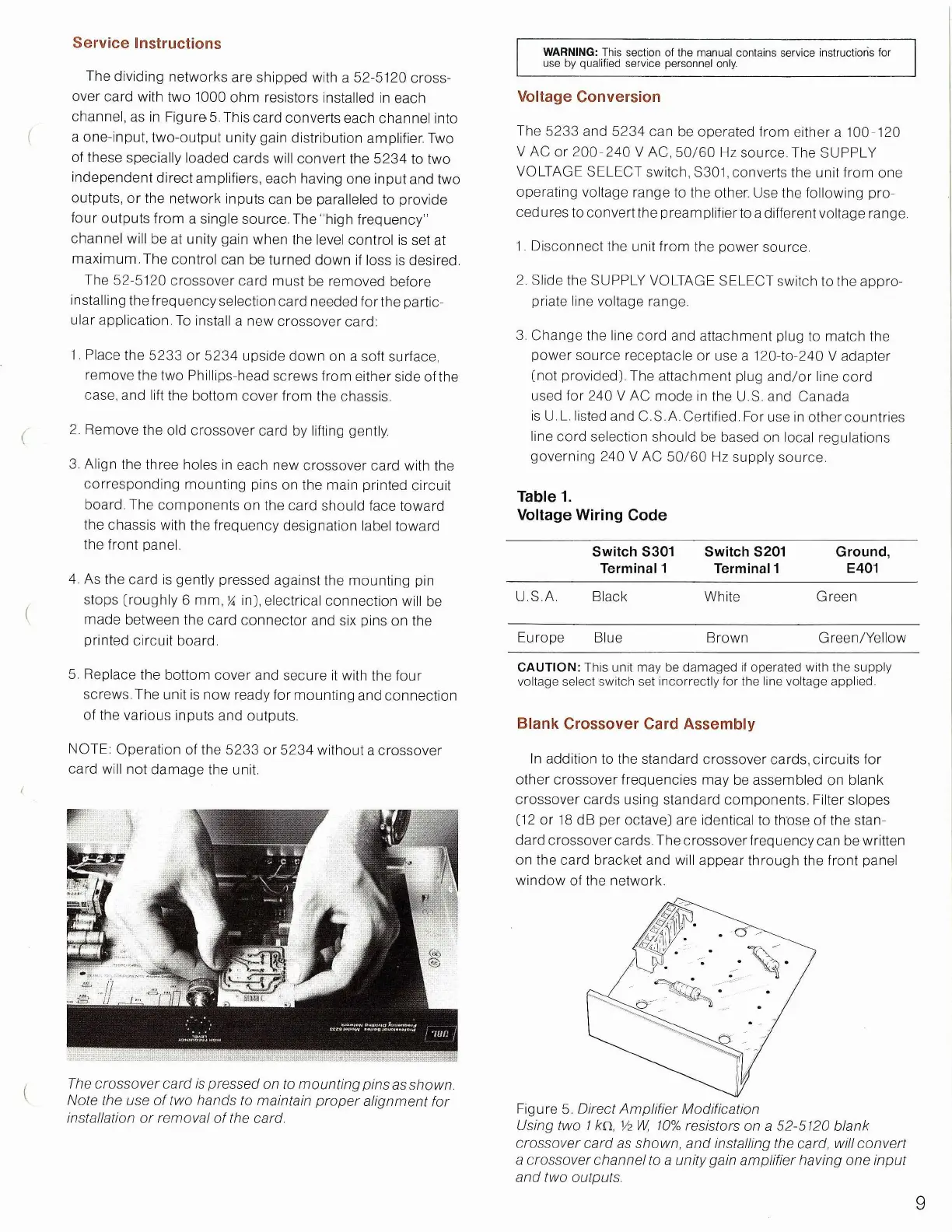
Figure 5. Direct Amplifier Modification
Using
two I /en, Vz W, 10%
resistors
on a 52-5120 blank
crossover
card
as
shown,
and installing the card,
will
convert
a
crossover
channel
to a
unity
gain amplifier having one
input
and
two outputs.
9
 Loading...