5234
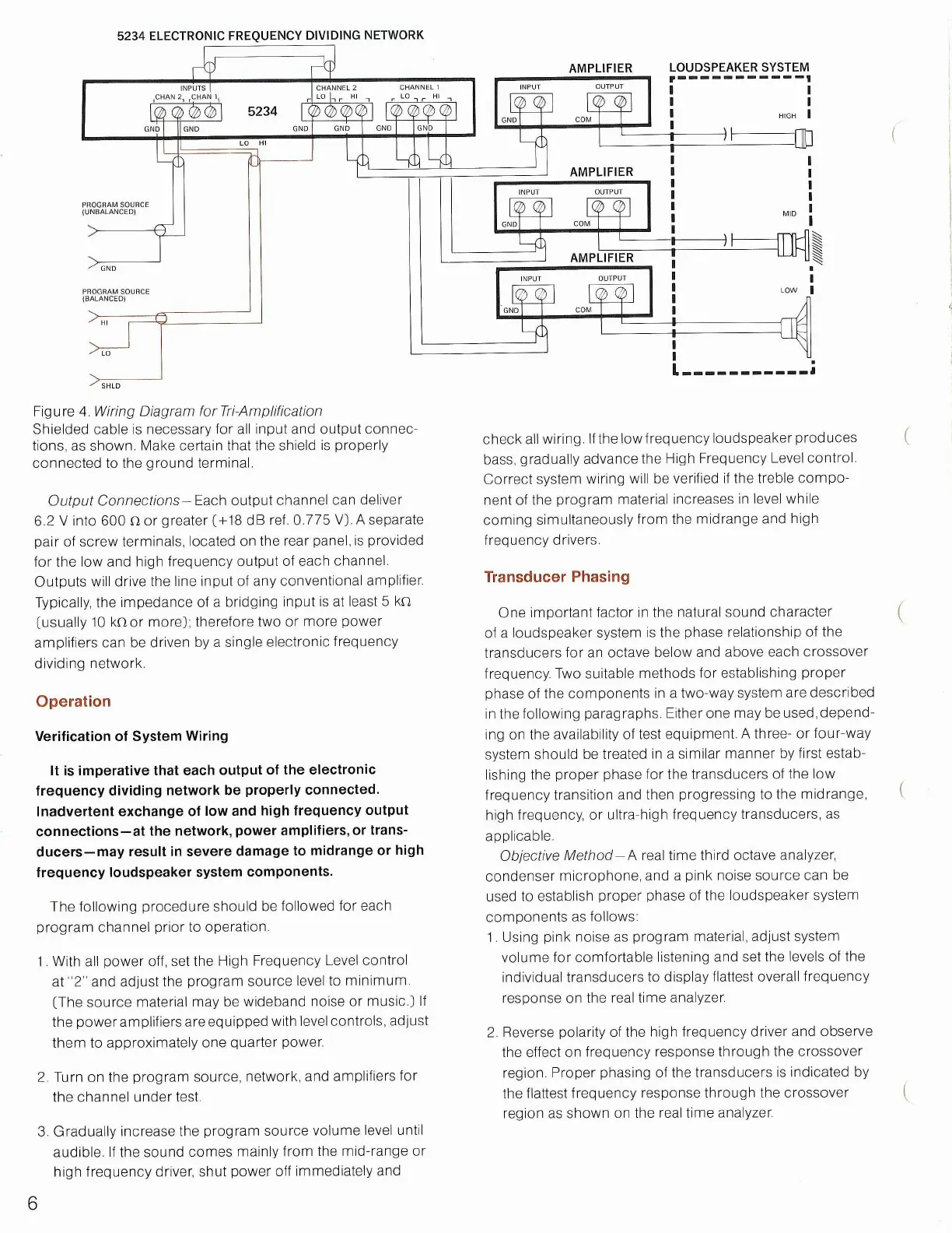
ELECTRONIC FREQUENCY DIVIDING NETWORK
5234
PROGRAM SOURCE
(UNBALANCED)
PROGRAM SOURCE
(BALANCED)
Output
Connections
-Each output channel can deliver
6.2 V into 600 Q or greater ( +
18
dB ref. 0.775 V}. A separate
pair of screw terminals, located on the rear panel, is provided
for the low and high frequency output of each channel.
Outputs will drive the line input of any conventional amplifier.
Typically, the impedance of a bridging input is at least 5 kn
(usually 10 knor more); therefore two or more power
amplifiers can be driven by a single electronic frequency
dividing network.
Operation
Verification of System Wiring
It is imperative that each output of the electronic
frequency dividing network be properly connected.
Inadvertent exchange of low and high frequency output
connections—at the network, power amplifiers, or trans-
ducers—may result in severe damage to midrange or high
frequency loudspeaker system components.
The following procedure should be followed for each
program channel prior to operation.
1.
With all power off, set the High Frequency Level control
at "2" and adjust the program source level to minimum
(The source material may be wideband noise or music.) If
the power amplifiers are equipped with level controls, adjust
them to approximately one quarter power.
2.
Turn on the program source, network, and amplifiers for
the channel under test.
3. Gradually increase the program source volume level until
audible. If the sound comes mainly from the mid-range or
high frequency driver, shut power off immediately and
AMPLIFIER
AMPLIFIER
check all wiring. If the lowfrequency loudspeaker produces
bass,
gradually advance the High Frequency Level control.
Correct system wiring will be verified if the treble compo-
nent of the program material increases in level while
coming simultaneously from the midrange and high
frequency drivers.
Transducer Phasing
One important factor in the natural sound character
of a loudspeaker system is the phase relationship of the
transducers for an octave below and above each crossover
frequency. Two suitable methods for establishing proper
phase of the components in a two-way system are described
in the following paragraphs. Either one may be used, depend-
ing on the availability of test equipment. A three- or four-way
system should be treated in a similar manner by first estab-
lishing the proper phase for the transducers of the low
frequency transition and then progressing to the midrange,
high frequency, or ultra-high frequency transducers, as
applicable.
Objective
Method-A real time third octave analyzer,
condenser microphone, and a pink noise source can be
used to establish proper phase of the loudspeaker system
components as follows:
1.
Using pink noise as program material, adjust system
volume for comfortable listening and set the levels of the
individual transducers to display flattest overall frequency
response on the real time analyzer.
2.
Reverse polarity of the high frequency driver and observe
the effect on frequency response through the crossover
region.
Proper phasing of the transducers is indicated by
the flattest frequency response through the crossover
region as shown on the real time analyzer.
6
AMPLIFIER
LOUDSPEAKER SYSTEM
HIGH
MID
LOW
Figure 4. Wiring Diagram forTri-Amplification
Shielded cable is necessary for all input and output connec-
tions,
as shown. Make certain that the shield is properly
connected to the ground terminal.
 Loading...