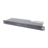
Do you have a question about the JBL M552 and is the answer not in the manual?
| Channels | 2 |
|---|---|
| Maximum Input Level | +20 dBu |
| Maximum Output Level | +20 dBu |
| Input Impedance | 20 kOhms |
| Output Impedance | 100 Ohms |
| Frequency Response | 20Hz to 20kHz |
| Signal-to-Noise Ratio | >90dB |
| Frequency Range | 20Hz - 20kHz |
| Power Supply | 50/60Hz |
| Weight | 6 lbs (2.7 kg) |
Details crossover frequencies, input/output impedance, noise, THD, and frequency response.
Covers enclosure dimensions and shipping weight for the unit.
Schematic details for CH1 and CH2 balanced/unbalanced input stages.
Schematic for the CH1 mono input stage.
Schematic for CH1 low and low-mid frequency adjustment.
Schematic for CH1 mid/high output level control and mute function.
Schematic for CH1 low output level control and mute function.
Schematic for CH2 low and low-mid frequency adjustment.
Schematic section for channel mono and range indicator LEDs.
Schematic for CH2 mid/high output level control and mute function.
Schematic for CH2 low output level control and mute function.
Schematic for final input and output signal processing stages.