About the Product
Operator Station
18 9831/5117-1 18
Operator Station
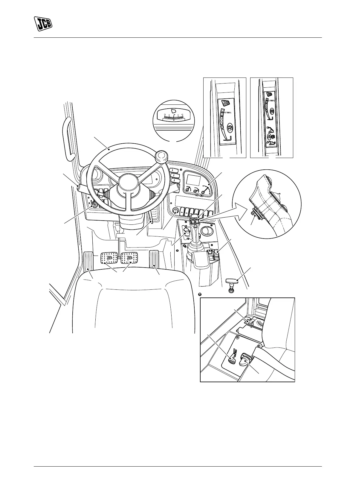
Component Locations
Figure 12.
A Steering WheelRefer to: Steering Wheel
(Page 62).
B Transmission Lever and Gear Selection
C Steer mode selectorRefer to: Steer Mode
Control (Page 68).
D Steering column adjustmentRefer to: Steering
Column (Page 62).
E Starter switchRefer to: Ignition Switch
(Page 20).
F HVAC (Heating Ventilation Air Conditioning)
controlsRefer to: Heating, Ventilating and Air-
Conditioning (HVAC) (Page 111).
G Service Brake PedalRefer to: Service Brake
Pedal (Page 64).
H Accelerator pedalRefer to: Accelerator Pedal
(Page 62).
J Handbrake/parkbrake mini leverRefer to: Park
Brake (Page 65).
K Hand throttle controlsRefer to: Hand Throttle
Control (Page 62).