EasyManuals Logo

jcb JCB380 Service Manual

jcb JCB380
51 pages
To Next Page IconTo Next Page
To Previous Page IconTo Previous Page
Page #46 background imageLoading...
Page #46 background image
03 - Attachments, Couplings and Load Handling
10 - Excavator Arm Quickhitch
06 - Hydraulic Quickhitch
03 - 8 9813/7500-2 03 - 8
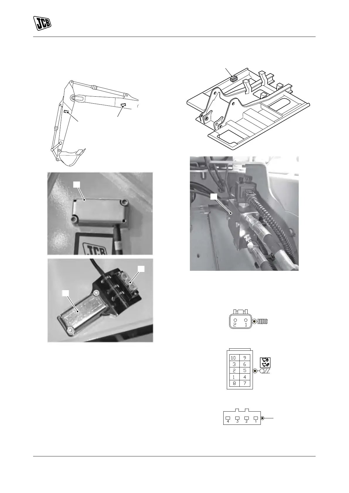
Component Identification
Figure 10.
A Dipper position sensor switch housing
B Boom position sensor switch housing
C LED (Light Emitting Diode) indicator
Figure 11.
A
A
A Solenoid valve (located in the hydraulic
compartment on the chassis)
Figure 12. Harness con-
nectors (C158, C157, C156)
Figure 13. Harness connector (C121)
Figure 14. Harness connector C095-X2 (green)

Other manuals for jcb JCB380

Questions and Answers:

Question and Answer IconNeed help?

Do you have a question about the jcb JCB380 and is the answer not in the manual?

jcb JCB380 Specifications

General IconGeneral
Brandjcb
ModelJCB380
CategoryExcavators
LanguageEnglish

Related product manuals