ASSEMBLY
- 1 -
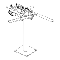
1) The bender may be mounted to anything rigid enough not to twist or move during the bending operation. To mount the bender
drill two 3/4" holes 2" inches apart through the mounting surface. The front cover shows the bender mounted on the optional
pedestal. NOTE: You can use the Frame Base to help position the holes the correct distance apart for drilling.
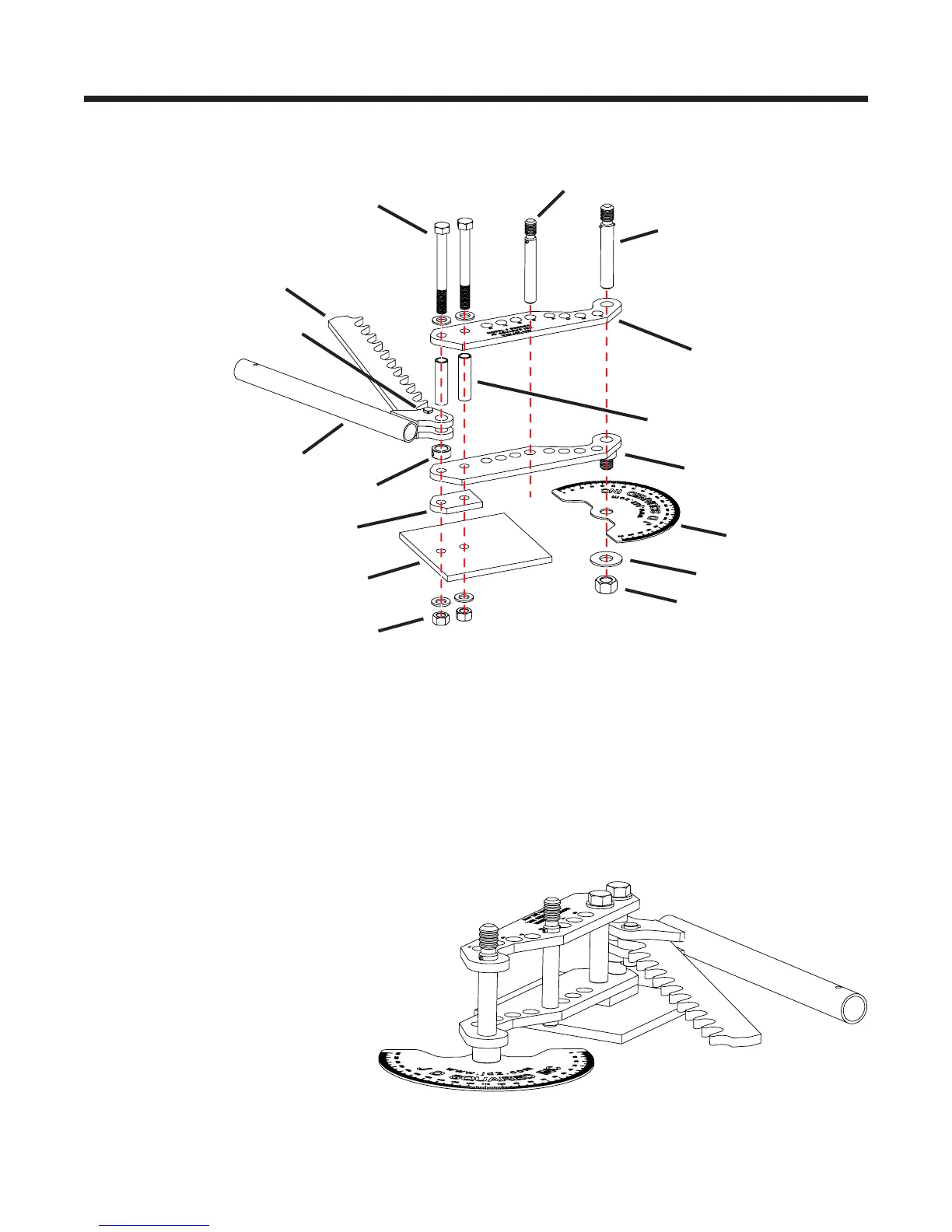
2) Assemble the bender's frame assembly as shown below.
A) Place the Frame Base on your mounting surface aligned with your drilled 3/4" holes.
B) Place the Lower Frame Link with the notched side to the left on top of the Frame Base aligned with the two 3/4"
holes.
C) AssembletheRatchetandRatchetLeverasshowningures1,2&4 using the 3/4" pin and two 1/8" spring pins. For
hydraulic adapter installation see page 3.
D) Place the Ratchet Lever and the 1" Collar on one of the two Spacer Tubes (1" OD tubes). Do not tighten collar.
E) InstalltheUpperFrameLink,Ratchetassemblyand1"SpacerTubesasshownabove.Handtightenthebolts.
F) Insert the 1" Frame Pin into the 1" Frame Link hole. Slide the 7/8" Frame Pin into hole #5. Tighten the 3/4" nuts as tightly
aspossible,whileinsuringthetwopinsareperfectlyverticalandslideeasilythroughtheirrespectiveholes.
G) Raise the Ratchet Lever to the middle
of the Tube Spacer and lock into
position with the 1" Collar.
H) InstallDegreePlateasshown.Use
only your hand to snug down the nut.
This nut is never wrench tightened.
This allows you to easily adjust the
Degree Plate while bending.
3/4"Bolts&Washers
Ratchet
Upper Frame Link
1" Frame Pin
1" OD Frame Spacer Tubes
Ratchet Lever
1" Collar
Frame Base
Your Mounting Surface
Figure 1 - Exploded view of the Frame Assembly with Degree Plate
Ratchet Pin
Lower Frame Link
Degree Plate
1"Washer
1"HexNut
3/4"NutsandWashers
7/8" Frame Pin
Figure 2 - Completed Frame Assembly with Degree Plate
 Loading...