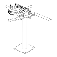
3) Followbar (Also referred to as the Pressure Die)
The Followbar is the component that presses the tubing into the forming die to create the bend. Shown in the illustration
below,itconsistsofthreemainparts:abackingblockandtwoinserts.Thismultipartdesignallowstheinserts,ifdamagedor
wornout,tobeinexpensivelyreplacedwithouthavingtopurchaseawholefollowbarassembly.TheInsertsarepermanent
moldcastfromaspecialbearinggradeanti-gallingmaterialtoprotectthetubingfromscratchingduringthebendingprocess
andthenCNCmachinedtosize.TheyaresilverishincolorbutareNOTaluminum.
Notice that one insert is slightly angled. This angle is
calculatedandmachinedintothebackingblockto1/1000
of a degree from theoretically perfect for the tube size
and bend radius. This angle helps to support the tube or
pipeafter thepoint ofbend, greatly reducingattening.
Whenbending,theangledinsertwillalwaysbecloserto
theformingdie,andtheU-strapforthatmatter,thanthe
straight insert.
A5/16"diameterrollpinisinstalledtoholdthefollowbar
in position while loading. When the followbar is in the
bender, theinsert groovesmust ride slightlylower than
the forming die's groove. This allows the followbar to RISE
underpressure.Ifthepinextendedtoofar,thefollowbar
would bind under pressure.
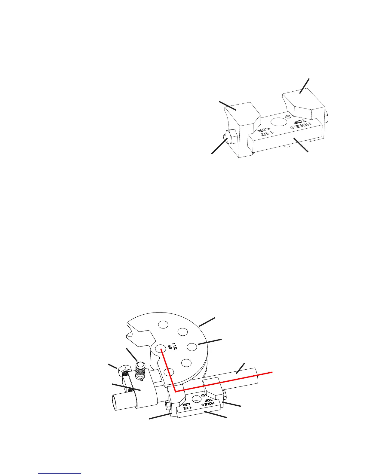
COMPLETEROUNDGROOVEDIESET
Below is pictured all of the components which make up a complete die set for round tubing or pipe. You can see two red
linesdrawnat90degreesapart.Theselinesaremarkedas1and2.Line1runsfromthecenteroftheformingdie'scenter
holetoapproximatelythemiddleoftheangledrearinsert.Line2runsfromthatpointparalleltothetubing.Thisillustrates
the basic principle of how the components relate to each other. It is vital that when bending the rear insert is positioned as
shown.Forexample,supposethefollowbarinengravedwithhole6asshown,butyouinstallitinhole7.Therearinsertwill
be shifted to the right of line 1 and the angle machined into it will have no effect during bending. This will generally cause
atteningofthetubing'soutersideandmayalsocausewrinkling.Ifyouexperiencethisproblemandyouhavethefollowbar
installedinthecorrecthole,therearinsert'sbendingpositioncanbeeasilychecked.Simplyplaceashortpieceoftubinginto
the bender as if your were actually going to bent it. Apply enough bending force to remove any play but not actually bend the
tubing.Nowholda90degreecarpenter'ssquareabovethebendersothatitsoutsideedgesarepositionedsimilartothered
lines shown. The center of the angled rear insert should be roughly at the corner of the square. I say roughly because some
diesaredesignedtoshifttheinsertslightlytotheleftorrightofcentertoimprovebendquality.However,thiswillgenerally
belessthan1/4".Ifasintheexampleabove,youplacedthefollowbarinthewronghole,theinsertwillbeverynoticablyoff
center and almost always to the right of red line 1.
Followbar
Drive holes (5)
U-StrapPin
U-StrapBolt
Tube
Angled Insert
Straight Insert
Figure 10 - Die set components
U-Strap
1
2
Forming Die
- 5 -
Figure 9 - 1 1/2" OD Followbar Assembly
Rear
Angled
Insert
Front Straight
Insert
Backing
Block
1/2"
Locking
Bolts
 Loading...