REMOVAL AND INSTALLATION
COMBINATION FLASHER
WARNING: ON VEHICLES EQUIPPED WITH AIR-
BAGS, REFER TO GROUP 8M - PASSIVE RESTRAINT
SYSTEMS BEFORE ATTEMPTING ANY STEERING
WHEEL, STEERING COLUMN, OR INSTRUMENT
PANEL COMPONENT DIAGNOSIS OR SERVICE. FAIL-
URE TO TAKE THE PROPER PRECAUTIONS COULD
RESULT IN ACCIDENTAL AIRBAG DEPLOYMENT
AND POSSIBLE PERSONAL INJURY.
REMOVAL
(1) Disconnect and isolate the battery negative
cable.
(2) Remove the steering column opening cover
from the instrument panel. Refer to Steering Col-
umn Opening Cover in the Removal and Installa-
tion section of Group 8E - Instrument Panel Systems
for the procedures.
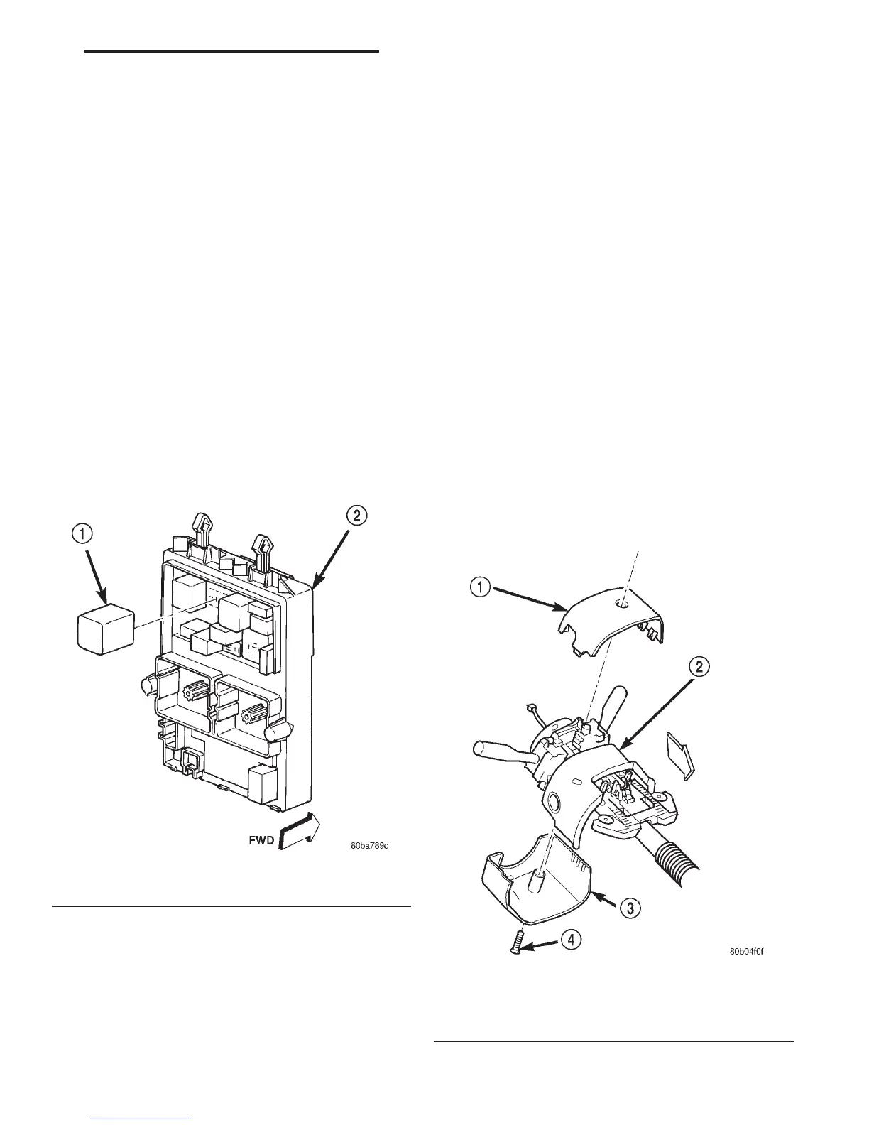
(3) Remove the combination flasher from the junc-
tion block (Fig. 4).
INSTALLATION
(1) Position the combination flasher in the proper
receptacle in the junction block.
(2) Align the combination flasher terminals with
the terminal cavities in the junction block receptacle.
(3) Push in firmly on the combination flasher until
the terminals are fully seated in the terminal cavities
in the junction block receptacle.
(4) Install the steering column opening cover onto
the instrument panel. Refer to Steering Column
Opening Cover in the Removal and Installation sec-
tion of Group 8E - Instrument Panel Systems for the
procedures.
(5) Reconnect the battery negative cable.
TURN SIGNAL AND HAZARD WARNING
SWITCH
WARNING: ON VEHICLES EQUIPPED WITH AIR-
BAGS, REFER TO GROUP 8M - PASSIVE RESTRAINT
SYSTEMS BEFORE ATTEMPTING ANY STEERING
WHEEL, STEERING COLUMN, OR INSTRUMENT
PANEL COMPONENT DIAGNOSIS OR SERVICE. FAIL-
URE TO TAKE THE PROPER PRECAUTIONS COULD
RESULT IN ACCIDENTAL AIRBAG DEPLOYMENT
AND POSSIBLE PERSONAL INJURY.
REMOVAL
(1) Disconnect and isolate the battery negative
cable.
(2) Remove the screw that secures the lower tilting
steering column shroud to the steering column multi-
function switch mounting housing (Fig. 5).
Fig. 4 Combination Flasher
1 – COMBINATION FLASHER
2 – JUNCTION BLOCK
Fig. 5 Steering Column Shrouds Remove/Install
1 – UPPER TILTING COLUMN SHROUD
2 – FIXED COLUMN SHROUD
3 – LOWER TILTING COLUMN SHROUD
4 – SCREW
WJ TURN SIGNAL AND HAZARD WARNING SYSTEMS 8J - 9
 Loading...