reduce buzzes, squeaks, and rattles even on the
bumpiest roads.
This type of construction also provides improved
energy absorption which, in conjunction with the
dual airbag modules and seat belts, helps to improve
occupant protection. This foundation structure also
serves as the air duct for the heating and air condi-
tioning system panel outlets, which greatly reduces
the number of components used over conventional
instrument panel construction.
Modular instrument panel construction allows all
of the gauges and controls to be serviced from the
front of the panel. In addition, most of the instru-
ment panel electrical components can be accessed
without complete instrument panel removal. If neces-
sary, the instrument panel can be removed from the
vehicle as an assembly.
Removal of the steering column opening cover and
knee blocker provides access to the steering column
mounts, the steering column wiring, the headlamp
switch, the electronic combination flasher, and much
of the instrument panel wiring. Removal of the glove
box provides access to the heating and air condition-
ing electrical and vacuum harnesses, the blower
motor relay, the radio antenna coaxial cable, the
lower passenger side airbag mounts, and additional
instrument panel wiring.
Removal of the instrument panel center bezel
allows access to the radio, the heating and air condi-
tioning controls, the accessory switches, the cigar
lighter, and the accessory power outlet. Removal of
the instrument cluster bezel allows access to the
instrument cluster. Removal of the cluster assembly
allows access to the cluster illumination and indica-
tor lamp bulbs, and more of the instrument panel
wiring.
Removal of the instrument panel top cover allows
access to the upper passenger side airbag mounts.
Instrument panel removal is required for service of
most internal components of the heating and air con-
ditioning system housing.
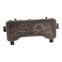
INSTRUMENT CLUSTER
DESCRIPTION
Two basic instrument clusters are offered on this
model: low-line, or high-line. Both clusters are elec-
tromechanical units that utilize integrated circuitry
and information carried on the Chrysler Collision
Detection (CCD) data bus network for control of all
gauges and many of the indicator lamps. These clus-
ters also incorporate a digital Vacuum Fluorescent
Display (VFD) for the odometer/trip odometer display
functions. Some variations of each cluster exist due
to optional equipment and regulatory requirements.
The low-line cluster includes the following analog
gauges:
• Fuel gauge
• Speedometer.
This cluster also includes provisions for the follow-
ing indicator lamps:
• Airbag indicator lamp
• Anti-lock brake system lamp
• Brake warning lamp
• Coolant temperature warning lamp
• Cruise-on indicator lamp
• Four-wheel drive (Part Time and/or Full Time)
indicator lamps
• Headlamp high beam indicator lamp
• Low oil pressure warning lamp
• Low washer fluid warning lamp
• Malfunction indicator (Check Engine) lamp
• Seat belt reminder lamp
• Sentry Key Immobilizer System (SKIS) indicator
lamp
• Turn signal indicator lamps
• Upshift indicator lamp (manual transmission)
• Voltage warning lamp.
The high-line cluster replaces some of the indicator
lamps found in the low-line cluster with analog
gauges. The high-line cluster includes the following
analog gauges:
• Coolant temperature gauge
• Fuel gauge
• Oil pressure gauge
• Speedometer
• Tachometer
• Voltmeter.
The high-line cluster also adds a check gauges
lamp and a low fuel warning lamp to the remaining
indicator lamps found in the low-line cluster.
Both instrument clusters feature circuitry that has
a self-diagnostic actuator test capability, which will
test each of the CCD bus message-controlled func-
tions of the cluster by lighting the appropriate indi-
cator lamps and positioning the gauge needles at
several predetermined locations on the gauge faces in
a prescribed sequence. For more information on this
function, refer to Instrument Cluster in the Diag-
nosis and Testing section of this group.
The instrument cluster circuitry also integrates a
chime tone generator and a timer circuit. These
items replace the chime or buzzer module, and the
separate timer circuit for the rear window defogger
system. Refer to Chime Warning System in the
Description and Operation section of Group 8U -
Chime/Buzzer Warning Systems for more information
on the chime functions of the instrument cluster.
Refer to Rear Window Defogger System in the
Description and Operation section of Group 8N -
8E - 2 INSTRUMENT PANEL SYSTEMS XJ
DESCRIPTION AND OPERATION (Continued)