EasyManua.ls Logo

Jerguson MTII4200 Series - User Manual

Jerguson MTII4200 Series
7 pages
Print Icon
To Next Page IconTo Next Page
Loading...
The Clark Reliance Corporation
16633 Foltz Industrial Parkway | Strongsville, OH 44149 | Telephone +1 (440) 572-1500 Facsimile: +1 (440)-238-8828
Email: sales@clark-reliance.com
| Web Site: www.clark-reliance.com
Specialists in Liquid Level Indication
1. INTRODUCTION
The Jerguson Model MTII4200 is a 4-20 mA, loop-powered HART compatible level transmitter intended to be used in
conjunction with the Jerguson Magnicator II magnetic liquid level gage.
The part number designator for the MTII4200 can be found below.
MTII4200-#-#-#-#-#-#-###/###
COMM OPTION:
H=4-20mA w/ HART
HOUSING:
A= ALUMINUM w/ WINDOW (STD.)
S= STAINLESS STEEL w/ WINDOW
BA= ALUMINUM w/o WINDOW
TRANSMITTER ORIENTATION:
A= TOP LEFT HAND (STD.)
B= TOP RIGHT HAND
C= BOTTOM RIGHT HAND
D= BOTTOM LEFT HAND
ALARM SETTING:
L= 3.85 mA (DEFAULT)
H= 22.5 mA
MAX SENSING LENGTH
IN INCHES, ON 6 INCH INCREMENTS
LCD DISPLAY:
M= mA OUTPUT (DEFAULT)
I= INCHES
P= PERCENTAGE
ACTIVE SENSING LENGTH
IN INCHES
MOUNTING STYLE:
S= STRAIGHT (STD.)
H= HIGH TEMP EXTENDED
There are two main components that make up the MTII4200. These two components are the electronics housing and the
sensor housing (see Figs. 1 & 2). These two components are assembled at the factory and should not be separated in
the field.
Figure 1. MTII4200-H-A-D-x-x-S-xxx/xxx Straight Bottom Left Hand Assembly
MAX ACTIVE SENSING LENGTH
(3.500)
DETERMINED BY SE
POSITION AT ASSEMBLY
FOR V19961-E1= 9.313 (REF.)
FOR V20816-E6 & V21037-T= 8.688 (REF.)
Section: M500
Bulletin: M500.31
Date: 01-26-12
Supersedes: 04-22-08
MTII4200 level Transmitter
Installation, Operation &
Maintenance Instructions
Question and Answer IconNeed help?

Do you have a question about the Jerguson MTII4200 Series and is the answer not in the manual?

Summary

1. INTRODUCTION

MODEL NUMBER DESIGNATION

Describes the structure and options for part number designator for the MTII4200.

2. PRODUCT DESCRIPTION

2.1 MTII4200 TRANSMITTER SPECIFICATIONS

Lists the technical specifications for the MTII4200 transmitter including output, linearity, and operating conditions.

2.2 Theory of Operation

Explains the magnetostrictive sensing principle used by the transmitter to determine liquid level.

3. INSTALLATION;MOUNTING

Mounting

Provides instructions for physically attaching the transmitter to the Magnicator II chamber.

4. ELECTRICAL CONNECTIONS AND WIRING PROCEDURES

4.1 Cable Specifications

Details the requirements for cable type, size, and capacitance for proper operation.

4.2 Safety Recommendations for MTII4200 Transmitter

Outlines critical safety precautions for electrical connections and wiring.

5. SYSTEM CHECK

5.1 Loop #1 Test

Describes how to test the transmitter's output current by moving the float.

6. MAINTENANCE

6.1 Removal of Electronic Puck

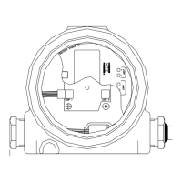
Step-by-step guide for safely removing the electronic module.

6.2 Installation of Electronic Puck

Step-by-step guide for safely installing the electronic module.

7. ADJUSTMENTS FOR MTII4200 TRANSMITTERS (via HART)

7.1 HART Quick Start

Provides initial steps for re-calibrating the transmitter using HART communication.

7.2 Calibration

Details the process for calibrating the zero and span points using the transmitter's buttons.

8. ALARM SETTINGS

9. SPARE PARTS

Jerguson MTII4200 Series Specifications

General IconGeneral
BrandJerguson
ModelMTII4200 Series
CategoryTransmitter
LanguageEnglish