Do you have a question about the JFY tech SUNTWINS 3300TL and is the answer not in the manual?
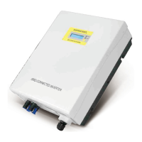
Provides an overview of the inverter's physical components and their labels.
Details the process for checking the inverter package contents for damage or missing items.
Outlines considerations for choosing a suitable location for inverter installation, focusing on ventilation and accessibility.
Provides step-by-step instructions on how to securely mount the inverter onto a wall using the provided frame.
Explains the overall system diagram and the labels used for connections on the inverter.
Guides on measuring grid voltage and frequency, and connecting the inverter to the AC power grid.
Details the procedure for connecting the PV panels to the inverter, including voltage limits and connector types.
Explains how to use the function key to view operating data and adjust settings like contrast and language.
Describes the messages displayed on the inverter's LCD screen, including operating states and main operating data.
Details how to establish data communication between the inverter and a computer using an RS232 serial port.
Explains the use of the RS485 serial port for connecting multiple inverters in a network.
Describes the RJ45 connectors used for RS485 communication, including pin definitions.
Explains how to connect multiple inverters in a daisy chain configuration using RS485.
The SUNTWINS series of solar inverters, manufactured by Shenzhen JingFuYuan Tech. Co., LTD. (JFY-tech), are transformerless devices designed for grid-connected photovoltaic (PV) systems. These inverters feature two channels of Maximum Power Point Tracking (MPPT) input, allowing them to efficiently convert direct current (DC) from PV generators into alternating current (AC) for feeding into the public grid. With a protection class of IP65, the units are suitable for use in various environmental conditions and are designed for high efficiency.
For your safety and the proper operation of the unit, it is crucial to read and understand the instructions provided in the manual before commencing any work. These instructions should be kept in an accessible location for all personnel working with the unit. Only professional technicians are authorized to install and operate these inverters.
A critical safety warning highlights the risk of electric shock from energy stored in capacitors. Users must wait at least 5 minutes after disconnecting the inverter from both the PV panel output and the AC grid before accessing any conductor parts of the input or output terminals. The units contain fuses, and for continued protection against fire risk, replacement fuses must be of the same type and ratings, with replacement performed by qualified service personnel.
The installation of the inverter must strictly adhere to the National Wiring Rules of Standard AS/NZS 3000 and all other relevant local standards and regulations. The package does not contain spare parts, and users are explicitly warned against removing the machine cover as there are no user-serviceable parts inside. Servicing should be referred to qualified service personnel, and for repair inquiries, contact your reseller. Qualified service personnel must be aware that both AC and DC voltage sources are terminated inside these units, requiring individual disconnection of each circuit before servicing. It is imperative to read and understand all instructions and safety symbols in the manual before installation and commissioning. Connection to the AC grid is permitted only after receiving approval from the administering authority, as mandated by national and state interconnection regulations, and must be performed by qualified personnel.
To prevent dangerous high voltage at connection cables, the entire surface of the photovoltaic panel should be covered with opaque material before connecting it to the equipment. The SUNTWINS inverter is designed exclusively to feed power into the public utility grid and should not be connected to an AC source or generator, as this could cause severe damage. JFY-tech offers special types for such applications if needed. During operation, some parts and surfaces of the inverter, particularly the heat sink at the back, can become hot. To reduce injury risk, avoid touching these hot surfaces and keep flammable objects away. This version of SUNTWINS inverters is intended for use with panels connected in a "floating" manner, meaning positive and negative terminals are not connected to the ground.
The equipment features several safety labels, some with a yellow background, which must be read and fully understood prior to installation. Key symbols include:
The electrical installation must comply with all applicable local and national standards. Connection to the AC grid requires prior authorization from the utility. Upon receiving the package, inspect it for any damage (holes, cracks) and note any issues on receiving documents, signed by the carrier. Open the box carefully to check for internal damage and ensure all contents are present. If damage is found, contact the delivering carrier and your local supplier. The original packaging should be retained for potential future shipping for repairs.
The installation location should be well-ventilated, sheltered from direct sun, and allow fluent air flow. A suitable height from the ground is recommended for easy display readability. Sufficient room around the unit is necessary for easy installation and removal. Minimum clearances of 200mm (8 inches) are recommended around the inverter.
Mounting involves drilling 6 or 9 holes as illustrated in the manual, fixing the mounting frame, and then hanging the inverter onto the frame. Safety-lock screws are then used to secure the inverter. Ensure the inverter is not installed on a gradient surface, fits securely onto the bracket, and that safety-lock screws are properly inserted. The mounting wall should be strong enough to prevent vibrations during operation.
The SUNTWINS series are single-phase solar inverters with two MPPT input channels, converting DC from PV panels into single-phase 230Vac 50Hz AC for grid delivery. They are designed for on-grid PV systems. Installation and grid connection must follow local regulations and may require specific electricity consumption measuring devices. The inverter operates only when connected to the AC grid and cannot function as a stand-alone unit.
The inverter's bottom features connections for PV input (MC4 terminals for each channel) and RS232 (for monitoring via a special cable). For AC grid connection, measure the grid voltage and frequency (230VAC/220VAC, 50Hz, single phase). Open the AC switch and the AC terminals cover to connect AC wires. Recommended wire diameters and cross-sectional areas are provided based on the inverter model. For PV panel (DC input) connection, ensure the maximum open circuit voltage (Voc) of each PV string is less than 500VDC for SUNTWINS 4000TL and 5000TL models. Input wire length should be less than 30m. MC4 connectors are used for PV array terminals. To maximize output, two independent PV array groups are recommended for the DC input. Crucially, ensure correct polarity when connecting PV panels to the DC switch and then to the inverter terminals. Incorrect polarity can permanently damage the unit. Confirm the short-circuit current of the PV string is less than the inverter's maximum DC input current. High voltages exist when PV panels are exposed to the sun, so avoid touching live components and handle terminals carefully. The manual recommends a specific connecting way to avoid electromagnetic interference. Before connecting, verify the polarity and voltage values using a proper gauge.
For SUNTWINS 5000TL, the AC output side requires an overcurrent protective device rated 32A with a maximum breaking capacity of 6KA. For SUNTWINS 4000TL, it's 25A, 6KA. For SUNTWINS 3300TL, it's 20A, 6KA.
The front panel features an LCD screen, two LEDs (ALARM and POWER), and one function key. The LCD displays operating data, situations, and warning/error codes. The ALARM LED indicates a fault, while the POWER LED signifies normal operation. The function key allows setting parameters and display language. The LCD backlight automatically turns off after 10 seconds to save power. Users can press the function key to view operating data or to lock/unlock the display message.
During operation, do not place any items on the inverter, and avoid touching the heat sink as it can become very hot. Step 1: Ensure AC and DC cables are correctly connected, and unused DC plugs and AC terminal covers are sealed. Step 2: Connect the DC and AC switches. The inverter will start automatically if sufficient DC power is available from the PV strings. The inverter transitions through three states:
The inverter is user-friendly, displaying error or warning information on the LCD. Common messages include:
RS232: The inverter supports data communication via an RS232 serial port. Connect the inverter to a computer using a special JFY-tech RS232 cable, with a communication distance below 10m. Only JFY-tech's specific cable works, but extended cables can be purchased locally. RS485 (optional): For communication with multiple inverters, an RS485 serial port is available. Ethernet cables are used, with only three wires (two signal, one ground) applied. The inverter has two RJ45 sockets for input and output ethernet cables, which are connected in parallel. Up to 31 inverters can be daisy-chained, with a recommended maximum length of 1000m. Each unit automatically receives an RS485 address via JFY monitoring software. A 120Ω terminal resistor must be installed at the last inverter in the chain, even if only one inverter is present. JFY-tech provides a special RJ45 socket with this resistor. For safe communication, an isolating RS232-485 adapter is recommended between the first inverter and the computer, though non-isolating adapters can also be used.
After correctly connecting the RS232 or RS485 link, install and open the JFY monitoring software "JFY communicator" from the provided CD. This software allows users to monitor the inverters, with detailed information displayed on the right side of the main interface. Refer to the "JFY communicator user's manual" on the CD for detailed settings and functions.
The inverter is designed to be maintenance-free, simplifying daily operation.
JFY-tech provides a 60-month warranty period for SUNTWINS Series PV Grid-tied inverters and a 24-month warranty for system accessories. The warranty period begins from the date of goods receipt from distributors. Warranty evidence includes the purchasing invoice and product series number. If clients fail to provide these documents, JFY-tech will calculate the warranty start date from 2 months after the ex-factory date. The warranty covers damages due to defective design or manufacture, evaluated by distributors and JFY-tech.
The warranty does not cover:
Report defective devices with a brief error description to JFY-tech's distributors. If a replacement is agreed upon, an equivalent device (matching model and age) will be sent, and the remaining warranty entitlement transfers to the replacement device. The replacement is shipped within 2 working days. The defective device should be packed in the transport packaging for return to the distributor. On-site service for re-installation must be negotiated with distributors in advance by the end customer. All warranty services within the warranty period are free of charge.
| Model | SUNTWINS 3300TL |
|---|---|
| Type | Grid-tied Inverter |
| Max. DC Voltage | 550 V |
| Maximum DC Input Voltage | 550 V |
| Number of MPP Trackers | 2 |
| Max. AC Power | 3300 W |
| Maximum AC Output Power | 3300 W |
| Nominal AC Voltage | 230 V |
| Rated AC Output Voltage | 230 V |
| AC Output Frequency | 50/60 Hz |
| Maximum Efficiency | 97.5% |
| European Efficiency | 96.5% |
| Cooling Method | Natural Convection |
| Operating Temperature Range | -25°C to +60°C |
| Protection Level | IP65 |
| Communication | RS485, Wi-Fi (optional) |
| Nominal AC Power | 3300 W |
| Rated AC Output Power | 3300 W |
| Humidity | 0-100% (non-condensing) |