This document is an operation manual for Jianken JG series High-Speed Spindle Motors, including High-Speed Motors and High-Speed Grinding Heads. The manual aims to provide users with comprehensive instructions for installation, operation, routine maintenance, preservation, and precautions to ensure proper use and longevity of the equipment.
Function Description
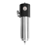
The Jianken JG series High-Speed Spindle Motors are designed for high-precision applications in machining centers. These motors are primarily used for CNC drilling, milling, 3D engraving, precise grinding, and mold processing. They are characterized by high precision, small volume, high torque, stable running, and low sound. The JGL series, specifically, are high-precision automatic tool change spindle motors driven by an inverter, allowing for continuous adjustment of spindle speed by controlling frequency. The JGY series are permanent magnet synchronous pneumatic tool change spindles, featuring a rotor with permanent magnetic material and a redesigned stator winding with an inductive encoder. This design enables precise speed control in both clockwise and anti-clockwise motion, offering high power and high torque at low speeds, suitable for drilling, tapping, and milling. The JGD, JGH, and JGM series cover constant torque, constant power, and grinding motor spindles, respectively, all utilizing high-speed bearings with high precision and offering continuously variable speed.
Important Technical Specifications
The manual provides detailed specifications for various models within the JGL, JGY, JGD, JGH, and JGM series. Key parameters include:
JGL Pneumatic Tool Change Spindle Motor:
- Speed: Ranges from 12000 r/min to 60000 r/min.
- Power: Ranges from 1.5 kW to 13.5 kW.
- Voltage: Typically 220 V or 380 V.
- Frequency: Ranges from 400 HZ to 1000 HZ.
- Current: Ranges from 4 A to 27 A.
- Lubrication Mode: Primarily grease.
- Interface: ISO10, ISO20, ISO25, BT30, BT40.
- Cooling: Water-cooled.
- Features: Models include options with unclamp & clamp unit, and sensor unclamp & clamp unit, some with encoder sensor.
JGY Permanent Magnet Synchronous Pneumatic Tool Change Spindle:
- Speed: Ranges from 7500 r/min to 30000 r/min.
- Power: Ranges from 3.7 kW to 15 kW.
- Voltage: Typically 380 V.
- Frequency: Ranges from 250 HZ to 1200 HZ.
- Current: Ranges from 6 A to 30 A.
- Lubrication Mode: Grease.
- Interface: ISO20, BT30, BT40.
- Cooling: Water-cooled.
- Encoder: Inductive encoder for precise speed control.
JGD Constant Torque Motor Spindle:
- Speed: Ranges from 24000 r/min to 60000 r/min.
- Power: Ranges from 0.07 kW to 13 kW.
- Voltage: Ranges from 48 V to 380 V.
- Frequency: Ranges from 250 HZ to 1000 HZ.
- Current: Ranges from 1 A to 20 A.
- Collet Type: ER8, ER11, ER16, ER20, ER25, ER32.
- Cooling: Self-cooled or water-cooled.
JGH Constant Power Motor Spindle:
- Speed: Ranges from 7500 r/min to 24000 r/min.
- Power: Ranges from 1.5 kW to 11 kW.
- Voltage: Typically 220 V or 380 V.
- Frequency: Ranges from 250 HZ to 800 HZ.
- Current: Ranges from 4.2 A to 13 A.
- Collet Type: ER16, ER20, ER25, ER32, ER40.
- Cooling: Water-cooled.
JGM Grinding Motor Spindle:
- Speed: Ranges from 24000 r/min to 60000 r/min.
- Power: Ranges from 0.25 kW to 12.5 kW.
- Voltage: Ranges from 75 V to 380 V.
- Frequency: Ranges from 400 HZ to 1000 HZ.
- Current: Ranges from 1.6 A to 26 A.
- Nose Size: ER8, ER11, ER16, M6, M8, M121, M161.5, M141.5, M221.5, M24*1.5.
- Lubrication: Grease.
- Cooling: Water-cooled.
- Bearing Type: Various combinations of 7000 series bearings (e.g., 1/7000-1/708, 2/7005-1/7203).
General Specifications:
- Operating Ambient Temperature: -10°C to 40°C.
- Insulation Resistance: Stator insulation resistance should be 200 MΩ or more.
- Water-Cooling Requirements: Water amount 0.5 L/KW.min, minimum flow rate 1.5 L/min. A separate water tank with anti-rust inside is required, and water should be homothermal at 22 ±2°C.
- Air Supply Pressure (Pneumatic Spindles): 0.6~0.8 mpa, filtered to 25 µm.
- Air Sealed Pressure: 0.1~0.15 mpa (for dust & chips cleaning).
- Thermistor: 103F3950, R25:10K 1% B: 3950K, for temperature detection.
- Bearing Accuracy Grade: P4 for both front and back bearings.
Usage Features
- Inverter Matching: It is crucial to match the high-speed spindle motor with an appropriate inverter. Direct plugging to the power supply or incorrect inverter settings will damage the spindle.
- Pre-installation Check: Before installation, manually rotate the spindle nose to ensure smooth movement without blocks. Check stator insulation resistance.
- Mounting: Install the spindle into the mount bracket securely without any looseness. Spindles can be installed vertically or horizontally. Self-cooling spindles may require a radiator.
- Cooling System: For water-cooled spindles, ensure tubing joints are tight and strong to prevent leaks. Cooling liquid must flow smoothly.
- Cable Management: Power cables should be shielded and kept under 200 cm to prevent interference with CNC systems.
- Inverter Parameter Setup: Correctly set inverter parameters (rated frequency, maximum frequency, maximum voltage, overload current 120% of rated, overload protection time 8s, speed up/down 10-12s) according to spindle specifications.
- Rotation Direction: After power-on, inch the inverter to observe spindle rotation direction. It must match the arrow on the spindle. If not, exchange any two power cables. Running in the wrong direction can loosen the nut and cause danger.
- Air Supply (Pneumatic Spindles): Ensure air supply pressure is 0.6~0.8 mpa and filtered. "Air sealed" valve must be turned on at 0.1~0.15 mpa continuously during operation and tool changes to prevent contamination.
- Tool Change (JGL Series):
- Pressurize "air inlet" (0.6~0.7 mpa) for 3-5s to open the clamp.
- Pressurize "dust removal" (0.4~0.5 mpa) to clean the rotor's interior.
- Insert the tool holder until it reaches the cone top.
- Turn off "air inlet" and "dust removal" simultaneously, and discharge air from the cylinder to install the tool.
- Pressurize "air return" (0.6~0.7 mpa) for 5s to return the air cylinder to its initial position.
- To release the tool, turn on "air inlet" again.
- Sensor Connection (JGL Series): PNP type sensors are standard; NPN type must be specified. The sensor for "tool released" outputs a voltage signal when open. The sensor for "tool clamped" outputs a voltage signal when the tool holder is correctly in place. The spindle can only start when the "tool clamped" sensor outputs voltage.
- Starting Procedure: Spindle starting time is typically 5-20 seconds. Avoid prompt starts. Pre-heat the spindle by low-speed running for 10-15 minutes to properly lubricate bearings and reduce heat.
- Cooling Water Temperature: For water-cooled spindles, the water temperature should be 2°C higher than ambient, not exceeding 60°C. High temperatures accelerate grease failure, increase noise and vibration, damage bearings, and can burn coils.
- Tool Condition: Using abraded tools generates excessive axial and radial forces, accelerating bearing damage and increasing noise, eventually causing an axial gap. Replace worn tools promptly.
- Collet and Nut: If the collet cannot be removed or gets stuck, it's usually due to a damaged nut, which should be replaced.
- Cleanliness: Regularly clean wasted chips from the nut, collet, and rotor end to prevent scratching the rotor cone and affecting tool-clamping accuracy.
- Overloading: Avoid overloading the motor spindle during continuous operation. Overloading, inappropriate processing parameters, or exceeding designed capacity will shorten spindle lifetime.
- Cutting Fluid: Avoid splashing cutting fluid on the nut and rotor as much as possible, especially at high speeds, as it can enter bearings, destroy lubrication, and shorten bearing lifetime.
- Grinding Spindle: Ensure the grinding wheel's working line speed does not exceed the safety line speed to prevent accidents.
Maintenance Features
- Bearing Warranty: Bearings have a warranty period of 2500 hours. Other spindle parts have a one-year warranty. Maintenance becomes chargeable if users ignore "air sealed" protection, leading to fluid or chip ingress and bearing damage.
- Lubrication: High-speed spindles with grease lubrication require lubricant supply or replacement every 2000 hours. Replace lubricant immediately if bearings overheat or deteriorate.
- Lubricant Replacement: When replacing lubricant, clean the old grease and the bearing/cover with gasoline (grade 95# or above) three times or more. After drying, fill 1/2 or 1/3 of the cavity between the inner and outer rings with high-speed, high-temperature lubricant.
- Bearing Assembly: Angular contact bearings are commonly used. During assembly, maintain original bearing modes and positions to avoid shortening bearing lifetime.
- Bearing Replacement: Replace bearings when spindle vibration and noise significantly increase, indicating end-of-life. Ensure proper matching between the new bearing, shaft, and holes, and select bearings of the same type for assembly quality and accuracy.
- Spindle Coil Replacement: Note the mode, size, turns number, and wire gauge of the original coil. Losing this data or randomly changing the coil can deteriorate motor spindle performance or render it unusable.
- Long-Term Deactivation: For long-term storage, drain cooling water, inject anti-rust oil into the waterway, and oil the spindle collet, nuts, and front part. Treat the entire spindle with rust and damp proof.
- Restarting After Storage: If the spindle has been deactivated or stored for six months, replace the grease before use; otherwise, its lifetime will be affected.
- Bearing Lifetime Extension: Using tools with precise dynamic balancing can extend spindle bearing lifetime.
- Thermal and Short-Circuit Protection: If inverter thermal or short-circuit protection activates continuously, check for motor faults or excessively low settings on protection devices. The inverter can only operate once the fault is cleared.