EasyManua.ls Logo

JLG Skytrak 6036 - Service Manual

JLG Skytrak 6036
280 pages
Print Icon
To Next Page IconTo Next Page
Loading...
Service Manual
Model
6036
S/N 9B0499 & Before
8990151
Revised February 11, 2005

Table of Contents

Other manuals for JLG Skytrak 6036

Questions and Answers

  • K
    Kari DurhamJul 31, 2025
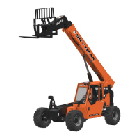
    What to do if JLG Front End Loader fails to extend or retract?
    • M
      Mathew SloanJul 31, 2025
      If your JLG Front End Loader fails to extend or retract, it could be due to a broken hydraulic line or connection leaks, a faulty extend/retract cylinder, faulty components in the hydraulic circuitry, or broken chains/chain connections. To resolve this, locate and repair any breaks or leaks, repair or replace the cylinder, troubleshoot and repair/replace faulty components, and repair or replace the chains.
  • R
    Raymond OrtizAug 5, 2025
    Why JLG Front End Loader fails to raise or lower?
    • H
      Harry WhiteAug 5, 2025
      If your JLG Front End Loader fails to raise or lower, the issue might stem from a broken hydraulic line or connection leaks, faulty hoist cylinder(s), or faulty components within the raise/lower hydraulic circuitry. To address this, locate and fix any leaks, repair the cylinder(s), and troubleshoot/replace any faulty components.
  • J
    Jordan TurnerAug 10, 2025
    What causes drooping chain or jerky boom on JLG Front End Loaders?
    • W
      William MillerAug 10, 2025
      A drooping chain or jerky boom extend/retract function on your JLG Front End Loader is likely caused by chains being out of adjustment. To fix this, readjust the chains.
  • E
    Elizabeth EdwardsAug 15, 2025
    Why is there excessive boom pivot pin wear on my JLG Front End Loader?
    • R
      Ryan HendersonAug 15, 2025
      Excessive boom pivot pin or cylinder pivot pin wear on your JLG Front End Loader is often due to improper grease intervals or worn bearings. Replace worn pins and lubricate at regular intervals, or replace the bearings and lubricate at regular intervals.
  • K
    kyleburnsAug 20, 2025
    How to deal with excessive wear pad wear on JLG Front End Loaders?
    • M
      Melissa WalkerAug 20, 2025
      Excessive wear pad wear on JLG Front End Loaders may be caused by improper wear pad shimming, or contaminated, corroded, or rusted wear pad sliding surfaces. Check the shim adjustment and shim properly, or prep the boom properly for long term storage.
  • J
    Jonathan ThomasAug 25, 2025
    What causes grille tilt failures in JLG Front End Loaders?
    • N
      Nancy CarterAug 26, 2025
      Grille tilt or auxiliary hydraulic circuit line failures in JLG Front End Loaders can be caused by improper hose tension or a misaligned hose sheave. Reset the hose sheave tension to resolve this issue.

Summary

SECTION 1 SAFETY PRACTICES

1.2 SIGNAL WORDS

Explains the meaning of DANGER, WARNING, and CAUTION signal words used in the manual.

SECTION 2 GENERAL INSTRUCTIONS

2.7 TORQUES

Lists torque values for fasteners and fittings, crucial for proper assembly and safety.

SECTION 3 BOOM

3.1 BOOM ASSEMBLY

Describes the boom assembly structure, consisting of inner, intermediate, and outer booms.

3.1.1 Inner Boom Replacement

Provides detailed steps for the removal, inspection, and installation of the inner boom.

3.1.2 Intermediate Boom Replacement

Details the procedure for removing, inspecting, and installing the intermediate boom.

3.1.3 Outer Boom Replacement

Outlines the steps for removing, inspecting, and installing the outer boom.

3.2 EMERGENCY BOOM LOWERING

Details emergency procedures for lowering the boom in case of engine power loss or hydraulic failure.

3.2.1 Loss of Engine Power or Hydraulic Pump Failure

Procedure to lower boom if engine power is lost or hydraulic pump fails.

3.2.2 Hydraulic Line Failure

Explains caution and procedures for lowering boom during a hydraulic line failure.

3.4 TROUBLESHOOTING

Provides a chart of common boom-related problems, their probable causes, and recommended remedies.

SECTION 4 OPERATORS CAB

4.2 MECHANICAL HAND CONTROLS

Identifies and describes the main mechanical controls in the operator's cab.

4.2.3 Boom Control and Grille and Frame Tilt Joysticks

Describes the operation and removal/installation of joysticks for boom and tilt controls.

4.3 MECHANICAL FOOT CONTROLS

Details the mechanical foot controls, including brake and throttle pedals.

SECTION 5 WHEEL ASSEMBLY, TIRES, AND AXLE

5.1 WHEEL ASSEMBLY AND TIRE

Covers general information, warnings, and types of wheels and tires used on the forklift.

5.1.2 Demounting Tire

Outlines the procedure for safely demounting a tire from the wheel.

5.1.4 Demounting Standard Tire from Three Piece Wheel

Provides specific instructions for demounting tires from three-piece wheels.

5.1.5 Demounting Optional Tire from Single Piece Wheel

Details the procedure for demounting optional tires from single-piece wheels.

5.1.11 Mounting Tire

Outlines the steps for mounting a tire onto the wheel assembly.

5.1.12 Mounting Standard Tire on Three Piece Wheel

Provides specific instructions for mounting standard tires on three-piece wheels.

5.1.13 Mounting Optional Tire on Single Piece Wheel

Details the procedure for mounting optional tires on single-piece wheels.

5.2 AXLE ASSEMBLY

Describes the components and functions of the axle assembly, including front and rear axles.

5.2.1 Axle

Details the removal and installation procedures for the axle assembly.

5.2.4 Axle Steering Joints

Describes the disassembly, cleaning, inspection, and installation of axle steering joints.

5.2.5 Steering Cylinder and Tie Rod

Details the removal, disassembly, cleaning, inspection, assembly, and installation of steering cylinders and tie rods.

5.5 TROUBLESHOOTING

Offers solutions for common problems related to the wheel, tire, and axle assemblies.

SECTION 6 DRIVE SHAFTS AND DROP BOX

6.1 DRIVE SHAFTS

Covers the removal, disassembly, cleaning, and installation of drive shafts.

6.2 DROP GEAR BOX

Details the inspection, removal, installation, and servicing of the drop gear box.

SECTION 7 TRANSMISSION, CLARK SERIES 18000

7.9 TROUBLESHOOTING

Provides a troubleshooting guide for common transmission problems, their causes, and remedies.

SECTION 8 ENGINE, PERKINS SERIES 4.236 AND T4.236

8.3 ENGINE ELECTRICAL SYSTEM

Refers to Section 10 for details on the engine's electrical system.

8.4 ENGINE FUEL SYSTEM

Covers the components and procedures for the engine fuel system.

8.4.7 Fuel Injection Pump

Explains the removal, installation, and setting of the fuel injection pump.

8.6 ENGINE REMOVAL

Details the step-by-step procedure for removing the engine and transmission assembly.

8.7 ENGINE OVERHAUL

Refers to the Perkins Engine Workshop Manual for engine overhaul procedures.

8.8 ENGINE INSTALLATION

Provides instructions for installing the engine and transmission assembly onto the forklift frame.

8.12 TROUBLESHOOTING

Offers a guide to diagnosing and resolving common engine problems.

SECTION 9 HYDRAULIC SYSTEM

9.1 CIRCUITS

Describes the various hydraulic circuits and their functions within the system.

9.1.1 Boom Raise;Lower

Details how hydraulic pressure is applied to the boom hoist cylinder pistons for raise/lower functions.

9.1.2 Boom Extend;Retract

Explains how hydraulic pressure is applied to the extend/retract cylinder piston for boom movement.

9.1.5 Brake Circuits

Details the hydraulic pressure application for service and park lock brake circuits.

9.1.6 Power Steering Circuit

Explains the hydraulic pressure application for the power steering circuit.

9.2 CYLINDERS

Covers the removal, disassembly, cleaning, inspection, assembly, and installation of hydraulic cylinders.

9.2.1 Boom Hoist Cylinder

Provides detailed steps for the removal, disassembly, and assembly of the boom hoist cylinder.

9.2.2 Boom Extend Cylinder

Details the procedure for removing, disassembling, and assembling the boom extend cylinder.

9.2.6 Steering Cylinder

Covers the removal, disassembly, cleaning, inspection, assembly, and installation of the steering cylinder.

9.3 VALVES

Covers the removal, repair, and installation of various valves in the hydraulic system.

9.3.1 Main Control Valve Assembly

Details the removal, repair, and installation of the main control valve assembly.

9.3.4 Steer Select Valve

Details the removal, cleaning, inspection, installation, and bleeding of the steer select valve.

9.4 PUMPS

Covers the removal, disassembly, cleaning, inspection, assembly, and installation of hydraulic pumps.

9.4.1 Main Tandem Pump

Provides detailed procedures for the removal, disassembly, and installation of the main tandem pump.

9.5 TROUBLESHOOTING

Provides a troubleshooting guide for common hydraulic system problems, their causes, and remedies.

SECTION 10 ELECTRICAL SYSTEM

10.1.1 Service Warnings and Recommendations

Provides critical safety warnings and recommendations for working on the electrical system.

10.2 WARNING DEVICES

Covers the horn, backup alarm, reverse switch, and warning lights.

10.4 CIRCUIT BREAKERS

Explains the function of circuit breakers in protecting the electrical system and how to replace them.

10.5 STARTING CIRCUIT

Details the operation and testing of the engine starting circuit, including components like starter and solenoid.

10.5.1 Testing Starter in Forklift

Provides general starter checks and detailed tests for voltage loss in the starting circuit.

10.5.2 How to Check Voltage Loss in the Starting Circuit

Outlines methods for checking voltage loss in the positive battery cable, starter solenoid, and negative battery cable.

10.5.3 Starter

Describes the starter motor's operation, removal, disassembly, and testing procedures.

10.6 CHARGING CIRCUIT

Covers the alternator and batteries, including their operation and testing.

10.6.1 Alternator

Details the alternator's operating principles, charging circuit, and troubleshooting procedures.

10.6.2 Batteries

Provides information on battery description, visual inspection, load testing, charging, and troubleshooting.

10.7 SWITCHES AND SOLENOIDS

Covers various switches and solenoids controlling forklift functions.

10.7.8 Steer Select Solenoid-Operated Valve

Explains the operation, removal, disassembly, cleaning, inspection, assembly, and installation of the steer select valve.

10.8.4 Warning Lights

Explains the function of warning lights, how to test them, and how to replace bulbs.

10.13 EMERGENCY BRAKING AND STEERING SYSTEM

Covers the low oil pressure switch and emergency hydraulic pumps.

10.14 TROUBLESHOOTING

Provides a troubleshooting guide for common electrical system problems, their causes, and remedies.

JLG Skytrak 6036 Specifications

General IconGeneral
Model6036
Operating Weight22, 500 lbs (10, 206 kg)
TransmissionHydrostatic
Lift Capacity6000 lbs (2722 kg)
Maximum Lift Height36 ft (10.97 m)
Engine Power74 hp (55 kW)