Models EELR538A and EELR539A
Models EELR540A and EELR541A
Installation, Operation and Maintenance
Page 4
Rev. 08/27/2021
15-18000-IOM-W.doc
RECEIVING
The shipment should be thoroughly inspected as
soon as it is received. The signed bill of lading is
acknowledgement by the carrier of receipt in good
condition of shipment covered by our invoice.
If any of the goods called for on this bill of lading are
shorted or damaged, do not accept them until the
carrier makes a notation on the freight bill of the
shorted or damaged goods. Do this for your own
protection.
NOTIFY
Challenger Lifts AT ONCE if any hidden
loss or damage is discovered after receipt.
IT IS DIFFICULT TO COLLECT FOR LOSS OR
DAMAGE AFTER YOU HAVE GIVEN THE
CARRIER A CLEAR RECEIPT.
File your claim with
Challenger Lifts promptly.
Support your claim with copies of the bill of lading,
freight bill, and photographs, if available.
Component Packing List
PART #
QTY/
LIFT
DESCRIPTION
15000 18000
12001 12001-18 1 POWER COLUMN ASS’Y
12002 12002-18 1 IDLER COLUMN ASS’Y
12004 1 OVERHEAD PACK
15-18000-HW-W 1 HARDWARE BOX
B12048S-1 4 ARM ASSEMBLY
12102
2
COLUMN EXT. (14’-6” O.A. HT.)
12022 COLUMN EXT. (16’-6” O.A. HT.)
12074 1 OVERHEAD SHUTOFF BAR ASS’Y
12045 1 OVERHEAD LIMIT SWITCH
12100
2
SYNC. CABLE ASS’Y (14’-6”)
12019 SYNC. CABLE ASS’Y (16’-6”)
B12069 4 ADAPTER EXTENSION (4”)
B12068 2 ADAPTER EXTENSION (8”)
12071 2 ADAPTER RACK
12093 4 ARM RESTRAINT ASSEMBLY
12119 12087-19
1
POWER UNIT – SINGLE PHASE
12089 12089-19 POWER UNIT – THREE PHASE
15-18000-LP-W 1 LITERATURE PACK
ACCEPTED OILS – Do not use oils with detergents
Hydraulic fluid is not provided with the lift shipment
-10
wt. anti-foam, anti-rust hydraulic / biodegradable oil
-Dexron III ATF
INSTALLATION
SAFETY REQUIREMENTS FOR INSTALLATION AND
SERVICE
Refer to ANSI/ALI ALIS (current edition)
I
MPORTANT: Always wear safety glasses while installing lift.
TOOLS (MINIMUM REQUIRED)
a. Tape measure, 16ft
b. Chalk line
c. 4ft level
d. 10” adjustable wrench
e. Standard open end wrenches 7/16”, 1/2",
(2) 9/16”, (2) 11/16”, 3/4"
f. 5/16” allen wrench
g. Needle nose pliers
h. Hammer drill with 3/4” diameter carbide tipped
bits
i. 2 lb hammer
j. Torque wrench: 150 foot pounds minimum with 1
1/8” socket
k. 12 ft. Step ladder
l. Anti-Seize lubricant (for arm pins and foot pad
screw threads and stop rings)
L
AYOUT
1) Layout the service bay according to the
architect’s plans or owners instructions (see Fig.
1b). Failure to install in this orientation can
result in personal and property damage. Be
certain that the proper conditions exist, see page
3.
2) Assemble column extension to column using
3/8”-16 x 3/4" lg Hex flange head bolt. Repeat for
opposite column and extension.
3) Erect and align both column assemblies.
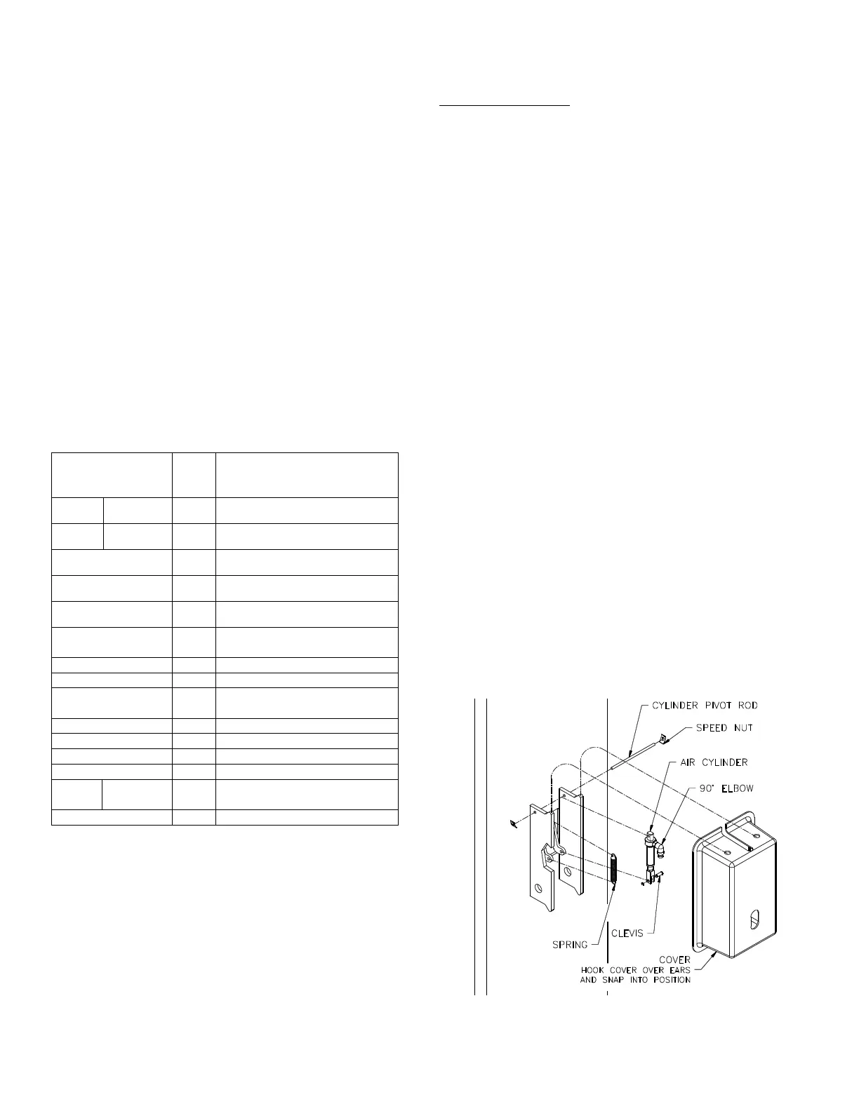
L
OCK RELEASE/PAWL
Fig. 2 – Locking Pawl Assembly
 Loading...