Do you have a question about the Johnson Controls 2951JR and is the answer not in the manual?
2951JR is listed for use in ducts. Refer to Duct Applications Guide A05-1004 for pendant mount.
Tests sensor electronics and panel connections by simulating smoke with a magnet.
Uses aerosol generators or canned smoke agents to test sensor response to smoke.
Utilizes specific accessories for remote testing of the sensor's functionality.
Requires a 90-day test period to ensure environment suitability for 0.2%-0.5% per foot settings.
Note that smoke detectors should only be used with guards if evaluated and found suitable.
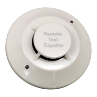
The 2951JR Intelligent Photoelectric Smoke Sensor is a sophisticated device designed for use in duct applications, integrating a state-of-the-art photoelectric sensing chamber with advanced communication capabilities. This sensor is an intelligent component within a larger fire alarm system, offering reliable smoke detection and remote testing functionalities.
The primary function of the 2951JR is to detect smoke within duct systems. It utilizes a photoelectric sensing chamber to identify the presence of smoke particles, triggering an alarm when a predefined obscuration level is reached. The sensor is designed to operate within a wide range of environmental conditions, including varying temperatures and humidity levels, making it suitable for diverse industrial and commercial settings.
The 2951JR is an intelligent sensor, meaning it communicates with a control panel using either FlashScan™ or CLIP (Classic Loop Interface Protocol) SLC communication modes. This intelligent communication allows the control panel to manage the sensor's operation, including its LED indicators and remote output. The sensor features two onboard LEDs that provide local, visible status indications. These LEDs can be controlled by the panel to display various operational modes, such as red blink, red continuous, green blink, green continuous, or off, depending on the system's status and configuration.
A key feature of the 2951JR is its remote test capability, which is particularly beneficial for duct applications. When used with a DNR/DNRW duct smoke detector, the sensor can be tested remotely using approved System Sensor test accessories like the RTS451, RTS451KEY, RTS151, or RTS151KEY. This eliminates the need for a physical test coil, simplifying maintenance and ensuring the sensor's functionality without direct access to the unit. The remote output can be synchronized with the LED operation or controlled independently, offering flexibility in system design and response.
The sensor also incorporates a tamper-resistant capability, designed to prevent unauthorized removal from its mounting bracket without the use of a specialized tool. This enhances the security and integrity of the fire alarm system.
The 2951JR is designed for straightforward installation and integration into compatible control panels. It requires a sensor base (supplied separately) and proper wiring according to the provided wiring diagram, adhering to the National Electrical Code and local regulations. The desired SLC address is set on rotary switches, allowing for unique identification within the system. Once installed, the sensor is secured into its base by pushing and turning it clockwise.
For optimal performance, Johnson Controls recommends spacing sensors in compliance with NFPA 72 guidelines. In low airflow applications with smooth ceilings, a spacing of 30 feet apart is suggested. Specific guidance for sensor spacing, placement, and special applications can be found in NFPA 72 and the System Smoke Detector Application Guide.
The sensor supports high sensitivity settings, specifically 0.2% to 0.5% per foot obscuration. This setting is intended for use in smoke-free, environmentally controlled environments such as computer rooms and clean rooms. When utilizing this high sensitivity, a 90-day test period is required to ensure the detector's environment is suitable. During this period, the detectors must operate continuously, and all environmental factors (temperature, humidity, airflow, occupancy) should be similar to the intended application. An electronic history file or printer must record all events associated with the detectors under testing. If no alarms or pre-alarms are recorded after 90 days, the system can be set to the tested pre-alarm level within the specified range.
Regular testing and cleaning are crucial for maintaining the optimal performance of the 2951JR. Before any maintenance, proper authorities must be notified, and the system or relevant zone should be disabled to prevent unwanted alarms.
The sensor can be tested in several ways:
If a sensor fails any of these tests, it should be cleaned and retested. If it continues to fail after cleaning, it must be replaced.
Dust covers are provided during shipping to offer limited protection against airborne dust. However, these covers must be removed before the sensors can sense smoke. It is also recommended to remove sensors prior to heavy remodeling or construction to prevent damage or contamination.
| Model Number | 2951JR |
|---|---|
| Category | Smoke Alarm |
| Type | Photoelectric |
| Frequency | 60 Hz |
| Hush Feature | Yes |
| Mounting | Ceiling or wall |
| Alarm Sound Level | 85dB at 10 feet |
| Humidity Range | 10% to 95% (non-condensing) |
| Interconnectable | Yes |
| LED Indicator | Yes (Green for power, Red for alarm) |
| Compliance | UL 217 |