LISTED COMPATIBLE
CONTROL PANEL
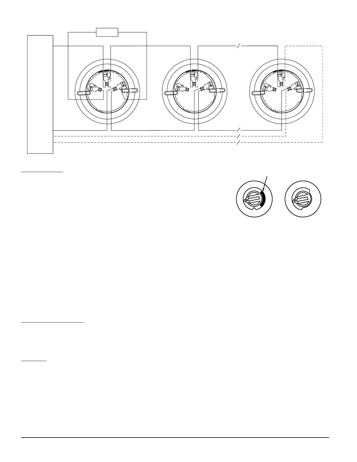
CLASS A OPTIONAL WIRING
WIRING GUIDE
All wiring must be installed in compliance with the National Electrical Code,
applicable local codes and the Authority Having Jurisdiction. Proper wire gaug-
es should be used. The installation wires should be color coded to limit wiring
mistakes and ease system troubleshooting. Improper connections will prevent
a system from responding properly in the event of a fire.
Remove power from the SLC communication line before installing sensors.
1. Wire the sensor base (supplied separately) per the wiring diagram, see
Figure 1.
2. Set the desired SLC address on the sensor address switches, see Figure 2.
Note: Some panels support extended SLC addressing. In order to set the
sensor above address 99 on compatible systems, carefully remove the stop on the upper rotary switch with thumb
as shown in Figure 2.
3. Install the sensor into the sensor base. Push the sensor into the base while turning it clockwise to secure it in
place.
4. After all sensors have been installed, apply power to the control unit and activate
the communication line.
5. Test the sensor(s) as described in the TESTING section of this manual.
TAMPER RESISTANCE
The sensor base includes a tamper proof feature which when activated prevents
removal of the sensor without the use of a tool. See the installation instruction
manual for the sensor base for details in using this feature.
TESTING
Before testing, notify the proper authorities that the system is undergoing maintenance, and will temporarily be out of
service. Disable the system to prevent unwanted alarms.
All sensors must be tested after installation and periodically thereafter. Testing methods must satisfy the Authority Having
Jurisdiction (AHJ). Sensors offer maximum performance when tested and maintained in compliance with NFPA 72.
A. Test Magnet (P/N M02-04-01 or M02-09-00)
1. Place the optional test magnet against the cover in the magnet test area, as shown in Figure 3, to activate the test
feature.
J200-08-00 2 I56-1931-01R
TENS
Breakaway Stop
ONES
9
10
11
12
13
14
15
8
7
6
5
4
3
2
1
0
9
8
7
6
5
4
3
2
1
0
Figure 2.
Rotary SLC Address Switches
Figure 1. Wiring Diagram
C0162-00
C0129-00
 Loading...