EasyManua.ls Logo

Johnson Controls NS8000 Series User Manual

Johnson Controls NS8000 Series
12 pages
To Next Page IconTo Next Page
Page #1 background imageLoading...
Page #1 background image
Vertical Wallbox-Mounted or Surface-Mounted
NS8000 Series Network Sensors Installation
Guide
Important (USA, Canada)
The NS Series Network Sensor is intended to provide an
input to equipment under normal operating conditions.
Where failure or malfunction of the network sensor
could lead to personal injury or property damage to
the controlled equipment or other property, additional
precautions must be designed into the control system.
Incorporate and maintain other devices, such as
supervisory or alarm systems or safety or limit controls,
intended to warn of or protect against failure or
malfunction of the network sensor.
Le NS Series Network Sensor est destiné à transmettre
des données entrantes à un équipement dans des
conditions normales de fonctionnement. Lorsqu’une
défaillance ou un dysfonctionnement du network sensor
risque de provoquer des blessures ou d’endommager
l’équipement contrôlé ou un autre équipement, la
conception du système de contrôle doit intégrer des
dispositifs de protection supplémentaires. Veiller dans ce
cas à intégrer de façon permanente d’autres dispositifs,
tels que des systèmes de supervision ou d’alarme, ou des
dispositifs de sécurité ou de limitation, ayant une fonction
d’avertissement ou de protection en cas de défaillance ou
de dysfonctionnement du network sensor.
Software terms
Use of the software that is in (or constitutes) this product
or access to the cloud or hosted services applicable to this
product, if any, is subject to applicable terms set forth at
www.johnsoncontrols.com/techterms. Your use of this
product constitutes an agreement to such terms. If you do
not agree to be bound by such terms, you may return the
unused product to your place of purchase.
North American emissions compliance
United States
This equipment has been tested and found to comply with
the limits for a Class B digital device, pursuant to Part 15
of the FCC Rules. These limits are designed to provide
reasonable protection against harmful interference in
a residential installation. This equipment generates,
uses and can radiate radio frequency energy and, if not
installed and used in accordance with the instructions,
may cause harmful interference to radio communications.
However, there is no guarantee that interference will not
occur in a particular installation. If this equipment does
cause harmful interference to radio or television reception,
which can be determined by turning the equipment
off and on, the user is encouraged to try to correct the
interference by one or more of the following measures:
Reorient or relocate the receiving antenna.
Increase the separation between the equipment and
receiver.
Connect the equipment into an outlet on a circuit
different from that to which the receiver is connected.
Consult the dealer or an experienced radio/TV
technician for help.
Warning (Part 15.21)
Changes or modifications not expressly approved by the
party responsible for compliance could void the user’s
authority to operate the equipment.
Canada
This Class (B) digital apparatus meets all the requirements
of the Canadian Interference-Causing Equipment
Regulations.
Cet appareil numérique de la Classe (B) respecte toutes
les exigences du Règlement sur le matériel brouilleur du
Canada.
Industry Canada Statement(s)
This device complies with Industry Canada licence-exempt
RSS standard(s). Operation is subject to the following two
conditions:
1. This device may not cause interference, and
2. This device must accept any interference, including
interference that may cause undesired operation of
the device.
Le présent appareil est conforme aux CNR d'Industrie
Canada applicables aux appareils radio exempts de
licence. L'exploitation est autorisée aux deux conditions
suivantes :
1. L'appareil ne doit pas produire de brouillage, et
2. L'utilisateur de l'appareil doit accepter tout
brouillage radioélectrique subi, même si le
brouillage est susceptible d'en compromettre le
fonctionnement.
Mounting
The NS Series Network Sensor can be surface mounted
or wallbox mounted. For wallbox-mounted installations,
mount the NS Series Network Sensor on a vertically
roughed-in wallbox only. Do not attempt to mount the
sensor on a horizontally roughed-in wallbox.
Note: Johnson Controls
®
does not supply the
required hardware for mounting.
*241125600007D*
Part No. 24-11256-00007 Rev. D
2021-04-15
NS8000

Other manuals for Johnson Controls NS8000 Series

Question and Answer IconNeed help?

Do you have a question about the Johnson Controls NS8000 Series and is the answer not in the manual?

Johnson Controls NS8000 Series Specifications

General IconGeneral
BrandJohnson Controls
ModelNS8000 Series
CategoryAccessories
LanguageEnglish

Summary

Important USA Canada Safety and Compliance

North American Emissions Compliance

Details FCC and Industry Canada compliance for digital devices, including warnings.

Mounting Instructions

Mounting Hardware Note

States that Johnson Controls does not supply the required hardware for mounting the sensor.

Location Considerations

Location and Handling Notes

Advise to locate sensors away from interference sources and handle with care, especially CO2 sensors.

Special Tools Required

Allen-Head Adjustment Tool

Identifies the Johnson Controls T-4000-119 Allen-head adjustment tool.

Flexible Allen-Head Tool

Identifies the JC 5309 Allen-head flexible tool.

Small Allen Wrench

Identifies the 1/16 in (1.5 mm) Allen wrench.

Installation Procedures and Warnings

Electric Shock Caution

Disconnect power before making electrical connections to prevent electric shock.

Important Wiring and Handling Precautions

Critical instructions on SA bus connections, housing, PCB, and simultaneous connection types.

Applications Overview

Setup and Adjustments for Fixed Display Model

Setup and Touchscreen Notes

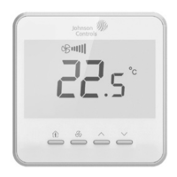
Notes on touch sensitivity, mounting, and activating the home screen backlight.

Adjusting Temperature Setpoint

Steps to adjust the temperature setpoint by 0.5 degree increments or continuously.

Adjusting Fan Speed

Steps to view and cycle through fan speed settings and save the selection.

Viewing Sensor Address and Firmware

Procedure to view the SA bus sensor address and firmware version by pressing the Menu icon.

Firmware Update Information

Information on automatic firmware updates for specific firmware versions and the CdL indicator.

Adjusting Temperature Units

Steps to toggle between Fahrenheit and Celsius temperature units.

Changing Home Screen Default Value

How to choose between displaying current temperature or setpoint on the home screen.

Selecting Setpoint Display Value

How to select whether current or setpoint temperature displays in the upper-right corner.

Selecting Maximum Fan Speed

Procedure to adjust the maximum fan speed displayed on the home screen.

Changing Decimal Separator

Steps to switch between a decimal point and a decimal comma separator.

Hiding Home Screen Icons

Guide to hiding specific display icons on the home screen for a cleaner interface.

Activating and Deactivating Screen Lockout

Instructions to lock the screen to prevent unauthorized changes and how to unlock it.

Adding Sensor Objects to MSEA

Explanation of configuring LCD model displays remotely via CCT and NS8000 firmware.

Setup and Adjustments for Warmer/Cooler Model

Increasing Temperature (W/C Model)

Steps to increase the temperature setpoint using the Up arrow on the W/C model.

Decreasing Temperature (W/C Model)

Steps to decrease the temperature setpoint using the Down arrow on the W/C model.

W/C Temperature Increment Note

Clarifies the increment step for temperature adjustment on W/C models.

W/C Temperature Decrement Note

Clarifies the decrement step for temperature adjustment on W/C models.

Network Sensor Addressing Setup

Information on configuring network sensor addresses using a three-position switch.

CO2 Altitude Compensation

CO2 Compensation Pressure Value Note

Important note to enter CO2 pressure values in hPa for accurate altitude compensation.

Repair Information

Technical Specifications

Supply Voltage and Current Consumption

Details supply voltage range and current draw for different sensor models.

Terminations and Network Addressing

Covers modular jack, screw terminal block wiring, and DIP switch addressing.

Communication and Sensor Types

Specifies communication rates and types of temperature and humidity sensors used.

Ambient Conditions and Resolution

Defines operating and storage ambient conditions and temperature resolution.

Accuracy Specifications

Details accuracy for temperature, humidity, and CO2 measurements under various conditions.

CO2 Sensor Operating Range and Lifespan

Specifies the operating range, time constant, and lifespan of the CO2 sensor.

Compliance and Product Information

PIR Occupancy Sensor Detection

Details the PIR sensor's detection range and angle.

Regulatory Compliance Marks

Lists compliance with US, Canadian, European, and Australian standards.

Dimensions and Shipping Weight

Provides physical dimensions and shipping weight of the network sensor.

UL Conformity Declaration

Details purpose of control, construction, pollution degree, and power supply.

CO2 Sensor Functionality

Explains the intended use of the CO2 sensor and safety precautions for its function.

Product Warranty and Software Terms

Information on product warranty coverage and software usage terms.

Contact Information

Regional Contact Points

Provides contact addresses for Johnson Controls in APAC, Europe, and NA/SA regions.

Branch Office and General Contact

Links to find local branch offices and general Johnson Controls contact information.

Related product manuals